
- Exam Center
- Ticket Center
- Flash Cards

Inductance Problems and Solutions for AP Physics
In this solved-problem tutorial, some of the most important examples and problems on self-inductance are solved which are at the AP physics C level.
All these problems are closely related to RL series circuit problems .
Solved Problem on Self-Inductance :
Problem (1): Find the self-inductance of a 100-turns solenoid with cross-sectional area $10\,{\rm cm^2}$ and length of $62.8\,{\rm cm}$.
Solution : The self-inductance of a solenoid depends only on its geometric factors which are its length $\ell$, number of turns $N$, and cross-sectional area $A$. All these factors are related together by the following formula \[L=\frac{\mu_0 N^{2} A}{\ell}\]Therefore, by putting values into above, we have \[L=\frac{(4\pi\times 10^{-7})(100)^{2}(10\times 10^{-4})}{62.8\times 10^{-2}}=2\times 10^{-5}\,{\rm H}\]The SI unit of area is $m^2$, so we converted the the given $cm^2$ to SI units as below \[\rm{1\, cm^{2}=(10^{-2}\,m)^{2}=10^{-4}\,m^2}\]
Are you getting ready for the AP Physics 2 exam? Read this:
AP Physics 2: Circuits Practice Problems with Answers
Problem (2): There is a solenoid with an inductance $0.285\,{\rm mH}$, a length of $36\,{\rm cm}$, and a cross-sectional area $6\times 10^{-4}\,{\rm m^2}$. (a) Find the number of turns of the solenoid. (b) Suppose at a specific time the emf is $-12.5\,{\rm mV}$ find the rate of change of the current at that time.
Solution : The self-inductance of a solenoid with length $\ell$, $N$ turns, and cross-sectional area $A$ is given by formula \[L=\frac{\mu_0 N^{2} A}{\ell}\]
(a) In this problem, the number of turns is unknown, so rearranging the above expression and solving for $N$, we get \[N^{2}=\frac{L\ell}{\mu_0 A}=\frac{(0.285\times 10^{-3})(0.36)}{(4\pi\times 10^{-7})(6\times 10^{-4})}\]Taking the square root of both sides, gets the number of turns of the solenoid $N=369$.
(b) A changing current causes a self-induced emf in the solenoid whose magnitude is determined by formula \[\mathcal{E}_L=-L\frac{di}{dt}\] Where the negative indicates the direction of the emf. Putting known values into above and solving for $di/dt$, we get \begin{align*} \mathcal{E}_L &=-L\frac{di}{dt}\\ \\ -12.5&=-0.285\,\frac{di}{dt} \\ \\ \Rightarrow \frac{di}{dt} &= +43.8\quad {\rm A/s}\end{align*} The positive shows that the current is increasing. On the other hand, we can deduce that the induced emf is in the opposite direction of the current in the circuit.
Problem (3): A $500$-turn solenoid have a cross-sectional area $20\,{\rm m^2}$. If its self-inductance is $20\,{\rm H}$, then find the length of the solenoid.
Solution : The self-inductance of a solenoid with $N$ turns, length of $\ell$, and cross-sectional area $A$ is given by the following formula \[L=\frac{\mu_0 N^{2} A}{\ell}\] Putting the values into the above formula and solving for the unknown length $\ell$, we get \[\ell=\frac{(4\pi\times 10^{-7})(500)^{2}(20)}{20}=0.314\,{\rm m}\] Thus, the solenoid has a length of $31.4\,{\rm cm}$.
Problem (4): A solenoid with $100$ turns have a length of $25\,{\rm cm}$ and loop's radius of $10\,{\rm cm}$. The current in it is changing constantly from $30\,{\rm A}$ to zero in $0.02\,{\rm s}$. What is the self-induced emf of the solenoid?
Solution : A changing current is related to a changing magnetic flux using the definition of self-inductance as $\Delta \Phi=L\Delta i$, where $\Phi$ is the total magnetic flux through a coil of wire having $N$ turns which is related to the flux through each turn as $\Phi=N\phi$. Thus, the self-inductance is \[L=\frac{\Phi}{i}=\frac{N\phi}{i}\] Recall that the magnetic flux formula through each turn of a solenoid is $\phi=(\mu_0 \frac N\ell i)A$ where $\ell$ and $A$ are the length and cross-sectional area of the solenoid, respectively.
Consequently, the inductance of a solenoid with $N$ turns is given by the below formula \[L=\frac{N\phi}{i}=\frac{\mu_0 N^{2}A}{\ell}\]As you can see, the solenoid inductance depends on the geometric factors $\ell$ and $A$ and on$\mu_0$ and does not depend on the variation of the current.
Thus, substituting the known values into the above formula, we get \[L=\frac{(4\pi \times 10^{-7})(100)^{2}(\pi (0.1)^{2})}{0.25}=1.5\,{\rm mH}\]
Problem (5): At the moment that the rate of change of the current through an ideal inductor is increasing as $0.064\,{\rm A/s}$, the magnitude of the self-induced emf is $0.016\,{\rm V}$. (a) What is the inductance of the inductor? (b) Let this inductor be a $400$-turns solenoid. How much magnetic flux passes through each turn of it when the current is $0.720\,{\rm A}$?
Solution : A time-varying current through a solenoid creates an emf which is related to each other by the following formula \[\mathcal{E}_L=-L\frac{di}{dt}\] Where the minus sign indicates the direction of the self-induced emf by Lenz's law. To find its magnitude, we should drop its negative.
(a) Applying the above equation and solving for unknown inductance $L$, we get \begin{align*} \mathcal{E}_L&=L\frac{di}{dt}\\ \\ 0.016&=L\,(0.064) \\ \\ \Rightarrow L&=0.25\quad {\rm H}\end{align*}
(b) Recall that when the current through an inductor is increasing, its magnitude varies as below \[I=I_0\left(1-e^{-Rt/L}\right)\] so at time $t=0$ the current is zero.
On the other hand, the definition of inductance as $N\Delta \phi=L\Delta i$ relates the difference in magnetic flux through each turn $\phi$ to the difference in the currents. We can use this definition to find the flux through each turn of a $N$-turn solenoid. \begin{align*} N\Delta \phi&=L\Delta i \\ N(\phi_2-\phi_1)&=L(i_2-i_1)\\ (400)(\phi_2-0)&=(0.25)(0.72-0)\\ \Rightarrow \phi_2&=0.45\,{\rm mWb}\end{align*}In the above, $\phi_1$ and $i_1$ are flux and current at time $t=0$ when there is no current in the circuit as well as the magnetic flux.
Problem (6): In a $500$-turn coil, the current is changing from $2\,{\rm A}$ to $2.05\,{\rm A}$ in the time interval $\Delta t$. During this time, the flux changes from $5000\,{\rm \mu Wb}$ to $5025\,{\rm \mu Wb}$. What is the self-inductance of the coil in henry?
Solution : Recall that where there is a changing magnetic flux, an electromotive force, emf $\mathcal{E}$, is produced in the circuit as \[\mathcal{E}=-\frac{d\Phi}{dt}\] On the other hand, the rate of change of the flux is related to the rate of change of the current using the definition of self-inductance $\Phi=LI$. Thus, this time the induced emf is written as \[\mathcal{E}=-\frac{d\Phi}{di}=-L\frac{di}{dt}\]
If time interval isn't infinitesimal we have \[\mathcal{E}=-\frac{\Delta \Phi}{\Delta i}=-L\, \frac{\Delta i}{\Delta t}\] Putting the known values into above formula, we get \begin{align*} -\frac{\Delta \Phi}{\Delta i}&=-L\frac{\Delta i}{\Delta t}\\ \\ \frac{5025-5000}{\Delta t}&=L \frac{2.05-2}{\Delta t}\\ \\ 25&=L\times 0.05 \\ \\ \Rightarrow L&= 500 \quad {\rm H}\end{align*}
Problem (7): At a given instant of time, the current and induced emf in an inductor are shown below. (a) Is the current increasing or decreasing? (b) If the induced emf is $25\,{\rm V}$ and the rate of change of the current is $10\,{\rm kA/s}$, then find the inductance of the inductor.

Solution : According to the section of Faraday's law of induction problems , self-induced emf is given by formula \[\mathcal{E}_L=-L\frac{di}{dt}\] Where $L$ is the self-inductance of the inductor and the negative also indicates the direction of the emf.
As you can see, if the rate of change of the current is increasing, $di/dt>0$, then self-induced emf is negative and directed in the opposite direction of the current and vice versa.
(a) In this problem, the current and emf are in the same direction, so the rate of change of current must be negative to cancel out the minus sign in the formula and create a positive emf.
Consequently, the current through this inductor is decreasing i.e. $di/dt<0$.
(b) Substituting the known values $di/dt=-30\,{\rm kA/s}$ and $\mathcal{E}_L=25\,{\rm V}$ into the self-induced emf formula and solving for the inductance $L$, we get \begin{align*} \mathcal{E}_L&=-L\frac{di}{dt}\\ \\25&=-L\left(-10\times 10^{3}\right)\\ \\ \Rightarrow L&=2.5\quad {\rm mH}\end{align*}
Problem (8): In the figure below, the current-vs-time graph for a $4\,{\rm H}$ inductor is depicted. What is the magnitude of the induced emf in the following time intervals? (a) $0\leq t \leq 2$ (b) $2\leq t \leq 5$ (c) $5\leq t \leq 6$
Solution : When the current in an inductor is changing, the magnetic flux is also changing. Consequently, according to Faraday's law, the induced emf is obtained as $\mathcal{E}=-L\frac{\Delta i}{\Delta t}$, where the negative is due to Lenz's law.
(a) In this time interval, the current increases from zero to $7\,{\rm A}$ so $\Delta i=7\,{\rm A}$ and \[\Delta t=2\times 10^{-3}\,{\rm s}\]Thus, the induced emf is \[\mathcal{E}=-4\times \frac{7}{2\times 10^{-3}}=-14\,{\rm kV}\] (b) Here, the current is decreasing and its rate of change is \[\frac{\Delta i}{\Delta t}=\frac{5-7}{3\times 10^{-3}}=-666.6\,{\rm A/s}\]. Thus, the self-induced emf is \[\mathcal{E}=(-4)\times (-666.6)=2666.6\,{\rm V}\] (c) In this time interval the current is also decreasing at a rate of \[\frac{\Delta i}{\Delta t}=\frac{0-5}{1\times 10^{-3}}=-5000\,{\rm A/s}\]Therefore, the induced emf is \[\mathcal{E}=(-4)\times (-5000)=20\,{\rm kV}\] As you can see the current and induced emf are in opposite directions only in the time interval $[0,2]$ and are in the same direction at other times which is expected from Lenz's law.
Problem (9): The current in a long solenoid with an inductance $L=0.5\,{\rm H}$ is varying as $I(t)=0.2\sin (500t)$. Find the maximum value of the induced emf in the solenoid.
Solution : The varying current produces an emf in an inductor (solenoid or coil of wire) with self-inductance $L$ as below \[\mathcal{E}_L=-L\frac{di}{dt}\] Thus, the self-induced emf in the solenoid is \begin{align*}\mathcal{E}_L&=-(0.5)\,\frac{d}{dt}\left(0.2\sin (500t)\right) \\ \\ &=-(0.5)(0.2)(500)\cos (500t)\\ \\ &=-50\cos (500t)\end{align*} Recall from trigonometry that the maximum value of cosine function is $1$ so the maximum value of the induced emf is $\mathcal{E}_L=-50\,{\rm V}$.
The negative shows the direction of the induced emf.
Problem (10): In the figure below, a $0.260\,{\rm H}$ ideal inductor (with zero resistance) is shown. A decreasing current passes through it at a uniform rate $di/dt=-0.0180$ in the direction shown. (a) Find the self-induced emf of the inductor. (b) Of points a and b, which is at higher potential?

Solution : According to Faraday's law, the self-induced emf of an inductor with inductance $L$ is determined as \[\mathcal{E}_L=-L\frac{di}{dt}\] Where the minus sign indicates the direction of the emf.
(a) Substituting the known values into the above formula, we get \[\mathcal{E}_L=-(0.260)(-0.0180)=+4.68\,{\rm mV}\]
(b) In the formula above, the direction of the induced emf depends on whether the current through an inductor is increasing or decreasing.
A decreasing current, $di/dt<0$, induces an emf in the same direction of the current to prevent further reduction of the current according to Lenz's law.
In this case, the inductor acts like a battery with the following polarities.

Consequently, as you can see from the above figure, the point $a$ is at a higher potential.
Author : Dr. Ali Nemati Date Published : 3/24/2021
© 2015 All rights reserved. by Physexams.com

- school Campus Bookshelves
- menu_book Bookshelves
- perm_media Learning Objects
- login Login
- how_to_reg Request Instructor Account
- hub Instructor Commons
- Download Page (PDF)
- Download Full Book (PDF)
- Periodic Table
- Physics Constants
- Scientific Calculator
- Reference & Cite
- Tools expand_more
- Readability
selected template will load here
This action is not available.

5.4: Inductors in Circuits
- Last updated
- Save as PDF
- Page ID 21537

- Tom Weideman
- University of California, Davis
Magnetic Field Energy
Inductors are what we were looking for – a device that goes into a circuit like a capacitor which involves magnetic rather than electric fields. Several chapters ago, we said that the primary purpose of a capacitor is to store energy in the electric field between the plates, so to follow our parallel course, the inductor must store energy in its magnetic field. We can calculate exactly how much is stored using tools we already have.
Suppose we start building up a current from zero into an inductor. With no current in it, there is no magnetic field and therefore zero energy, but as the current rises, the magnetic field grows, and the energy stored grows with it. We actually have a way of determining the rate at which the energy stored is growing from what we know already. There is no resistance to worry about here, so none of the energy is lost to thermal, which means that we can write the power as the product of the current and the voltage difference. As a reminder, power delivered to or by a battery is plus-or-minus the product of the current and the emf of the battery:
Figure 5.4.1 – Power Charging or Discharging a Battery

With the idea of an inductor behaving like a smart battery, we have method of determining the rate at which energy is accumulated within (or drained from) the magnetic field within the inductor. If the positive lead of our smart battery is facing the incoming current, it must be because the current is increasing. This results in an increase in the energy stored in the inductor, and sure enough, an increase in current corresponds to an increase in the magnetic field strength within the inductor. The reverse argument for an inductor where the current (and therefore field) is decreasing also fits perfectly. The math works easily by replacing the emf of the battery with that of an inductor:
\[\dfrac{dU_{inductor}}{dt} = I\left(L\dfrac{dI}{dt}\right)=LI\dfrac{dI}{dt}\]
We can now determine the energy within the inductor by integrating this power over time:
\[U_{inductor} = \int Pdt = \int \left(LI\dfrac{dI}{dt}\right)dt = L\int IdI = \frac{1}{2} LI^2\]
There is clearly a resemblance of this energy to that of a charged capacitor, though the parallels are not immediately obvious. It seems reasonable to relate the charge to the current, because in each case, these are what is accumulated within the device. This would mean that the parallel between capacitance and self-inductance is \(C\leftrightarrow L^{-1}\). This parallel only goes so far, however. For example, it doesn't work for \(Q=CV\). For energy considerations, however, it does work well, and we will see that this extends to field energy.
The potential energy stored within a solenoid (which, as we stated above, is pretty much the design of every inductor) can be written in terms of the magnetic field within. For this we need the self-inductance of a solenoid ( Equation 5.3.8 ), and the field of a solenoid ( Equation 4.4.13 ):
\[U_{solenoid} = \frac{1}{2}LI^2 = \frac{1}{2}\left(\dfrac{\mu_oN^2A}{l}\right)I^2 = \dfrac{1}{2\mu_o}\left(\dfrac{\mu_oNI}{l}\right)^2\left(A\cdot l\right) = \dfrac{1}{2\mu_o}B^2\left(A\cdot l\right)\]
The quantity \(A\cdot l\) is the volume of the solenoid, so dividing both sides by this gives the energy density of the magnetic field within the solenoid:
\[u_{solenoid} = \dfrac{U_{solenoid}}{volume} = \dfrac{1}{2\mu_o}B^2\]
Once again, the resemblance with the electric field version is clear, with the only difference being that the constant appears in the denominator here, while its electric counterpart appears in the numerator.
Enhancing Inductors
When we discussed capacitors, we found that we could alter their energy-storing capabilities by putting a dielectric between their plates. We have a similar option for inductors. We previously discussed the concepts related to magnetic fields in various substances, learning that substances can react in basically one of two ways: The magnetic dipoles in the substance can align with the field, or new dipoles can be induced which (according to Lenz’s law) align opposite to the field. The former we called paramagnetism (or, if the dipoles remain aligned after removing the field, ferromagnetism) and it augments the applied field. The latter we called diamagnetism, and it reduces the applied field. This contrasts with the case of electricity, where insulating materials can only react as dielectrics, and only act to reduce the field.
As in the case of electricity, we will introduce a physical constant known as the permeability , which, like the permittivity in the case of electricity, takes the place of the vacuum constant:
\[\text{electricity: } \epsilon_o \rightarrow \epsilon \;\;\;\;\;\;\;\; \text{magnetism: }\mu_o \rightarrow \mu \]
As with the case of electricity, we simply replace the vacuum permeability with the permeability of the substance to get the answers inside of matter. So Biot-Savart and Ampére’s laws are easily translated into more general forms:
\[\overrightarrow B = \dfrac{\mu}{4\pi}\int\dfrac{I\overrightarrow {dl} \times \widehat r}{r^2}\;\;\;\;\;\;\;\;\oint \overrightarrow B \cdot \overrightarrow {dl} = \mu I_{enclosed}\]
Notice from Biot-Savart's law that increasing the permeability for the same source increases the field strength (contrast this with the permittivity in the case of the Coulomb field). Therefore a permeability higher than the vacuum means the material is paramagnetic (and much higher than that is ferromagnetic). A value lower than the vacuum value corresponds to diamagnetism. Frequently materials are classified according to the percentage increase/decrease they provide to the total field compared to the vacuum case. That is:
\[\mu = \left(1+\chi_m\right)\mu_o\]
The constant \(\chi_m\) is called the magnetic susceptibility . This has a positive for substances that are paramagnetic and ferromagnetic, and a negative value for diamagnetic substances.
LR Circuits
It's time to add inductors into our circuit diagrams, so we need a new symbol:
As with any other object in a circuit, there will be a specific voltage drop across the device as we invoke Kirchhoff’s loop rule. The difference with this device it that its “smart battery” property makes it somewhat trickier than the other objects to determine the sign of the voltage change.
One reason to include an inductor in a circuit is to protect the circuit from current spikes (i.e. as a surge protector ). If the current changes dramatically and suddenly, then the inductor will respond by providing an emf that opposes the sudden change, reducing the amount that the current is able to change over a short period, protecting the system from potential damage. We will see some other effects that an inductor has on a circuit as well, starting with how it interacts in a circuit with a resistor.
Figure 5.4.2a – An LR Circuit with Growing Current
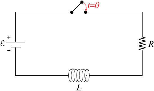
When the switch is first closed, the current "wants" to jump instantly from zero to satisfy \(\mathcal E = IR\), but the inductor doesn’t allow this, because it develops an emf to oppose sudden changes. We begin with the Kirchhoff loop rule (which provides a new challenge for us when it comes to inductors), then solve the differential equation as we did for the RC circuit previously. To use the loop rule, we need to label a current and choose a loop direction. For the case above, let's choose clockwise for both. Going around this loop, the battery provides a voltage increase of \(+\mathcal E\), and the resistor a voltage drop of \(-IR\). What about the inductor?
When the switch is closed, the current that points right-to-left for the inductor increases in the direction of the loop. As a result of Faraday's law, the inductor becomes a "smart battery" that acts to reduce the current, which means there is a voltage drop :
\[\mathcal E_{inductor} = -L\dfrac{dI}{dt}\]
With the current increasing, the derivative is positive, and since \(L\) is always positive, a voltage drop requires a minus sign. Before we put the loop equation together, let's ask how this might change if we had labeled the current differently or chosen a different loop direction. First, if we switch the direction of the current label to left-to-right, and leave the loop direction, then an increasing current will result in the left side of the "smart battery" being at higher potential, which means that in a clockwise loop, the inductor would give a potential increase, and we would have to use \(\mathcal E_{inductor} = +L\dfrac{dI}{dt}\). So it seems clear that we get the correct sign when we use the same convention as with the resistor – a minus sign when the current direction matches that of the loop direction, and a positive sign when the loop and current directions are opposite to each other.
Okay, so let's put together our loop equation and solve:
\[+\mathcal E -IR -L\dfrac{dI}{dt} = 0\]
We have obtained a solution to this differential equation before (with different variables) – Equation 3.5.8 . Following the same procedure to integrate this equation gives the result:
\[I\left(t\right) = \dfrac{\mathcal E}{R}\left(1-e^{-\frac{t}{\tau}}\right)\;,\;\;\;\;\; \tau\equiv \dfrac{L}{R}\]
Note that the time constant for this circuit is quite different from the one for the RC circuit. Most notably, higher resistance in an RC circuit results in a larger time constant – it takes longer for the charge to decay from the plates of the capacitor when the resistance is higher, because it keeps the rate of flow (current) lower. In this case, however, a larger resistance causes the current to decay faster (i.e. \(\dfrac{dI}{dt}\) is a more negative number):
\[\dfrac{dI}{dt} = \dfrac{1}{L}\left(\mathcal E - IR\right)\]
Faster decay means a smaller time constant.
Figure 5.4.2b – An LR Circuit with Growing Current
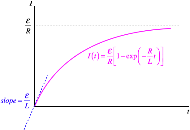
Let's check the extreme ends of this curve, to see if it makes sense. When the switch is first closed, the current grows at its greatest rate, but this is not infinity . That is, the current doesn't immediately jump to the value given by Ohm's law. The greater the inductance, the slower the initial growth in current is, since the slope of the current curve at \(t=0\) is inversely-proportional to \(L\). After a long time, the current-vs.-time curve flattens-out, and when the slope is zero, there is no emf induced in the inductor, which means that the current reaches the Ohm's law value – it gets to this point asymptotically.
Note that we can also witness this process in reverse – a circuit with an established current from which the battery is suddenly removed. In this case, we simply remove the \(\mathcal E\) term from the differential equation, and the result is exponential decay, like a discharging capacitor. The time constant for this case is the same as the case of growing current:
\[I\left(t\right) = I_oe^{-\frac{t}{\tau}}\;,\;\;\;\;\; \tau\equiv \dfrac{L}{R}\]
In terms of energy, it is easy to see what is going on here. The energy stored in the magnetic field is gradually converted into thermal energy energy by the resistor.
LC Circuits
Let's see what happens when we pair an inductor with a capacitor.
Figure 5.4.3 – An LC Circuit
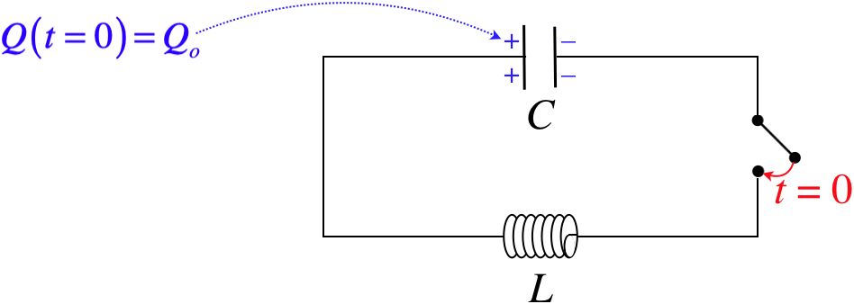
Choosing the direction of the current through the inductor to be left-to-right, and the loop direction counterclockwise, we have:
\[+\dfrac{Q}{C} -L\dfrac{dI}{dt}\]
Next we have to recall how to relate the charge on the capacitor to the current. When this current is positive, charge is leaving the capacitor, which means that a decrease in \(Q\) is related to a positive value of \(I\) according to:
\[I=-\dfrac{dQ}{dt} \]
Putting this in above gives the differential equation:
\[\dfrac{d^2Q}{dt^2} + \dfrac{1}{LC}Q = 0\]
This is another differential equation we have seen before, though it was not in this class . Yes, this is the same differential equation that comes about for a mass oscillating on a spring. The solution for \(Q\left(t\right)\) needs to be sinusoidal, since two derivatives of a sine or cosine function gives back a negative of itself (multiplied by a constant that comes from the chain rule). The solution to this particular case (with the starting charge at \(t=0\) given) is:
\[Q\left(t\right) = Q_o\cos\left(\omega t\right)\;,\;\;\;\;\;\omega\equiv \dfrac{1}{\sqrt{LC}}\]
Interpreting this result, we see that the charge actually sloshes back-and-forth between the plates (the charges on the plates actually eventually swap places!). We can also write down the equation for the current:
\[I\left(t\right) = -\dfrac{dQ}{dt} = Q_o\omega\sin\left(\omega t\right)=\dfrac{Q_o}{\sqrt{LC}}\sin\left(\omega t\right) = I_{max}\sin\left(\omega t\right)\;,\;\;\;\;\;I_{max}\equiv\dfrac{Q_o}{\sqrt{LC}}\]
We see that the current starts at zero, and grows to a maximum value, and this maximum occurs when the value of the sine is 1, which is the same time that the charge on the capacitor reaches zero. This actually gives us insight into the energy considerations for this circuit. Energy isn’t being converted to thermal energy by a resistor, so it has no way to exit, which means that the oscillations continue indefinitely. We know exactly how much energy the circuit starts with:
\[U_{tot}=\dfrac{Q_o^2}{2C}\]
When all of the charge is gone, the current hits a maximum, which means that all of the energy is then in the magnetic field. It’s easy to confirm that the energy is conserved:
\[U_{tot} = \frac{1}{2}LI_{max}^2 = \frac{1}{2}L\left(\dfrac{Q_o}{\sqrt{LC}}\right)^2 = \dfrac{Q_o^2}{2C}\]
Example \(\PageIndex{1}\)
Show that the total energy in the LC circuit remains unchanged at all times, not just when all the energy is in the capacitor or inductor.
The energy stored in the system at a time \(t\) is the sum of the energies stored in each device:
\[U\left(t\right) = \frac{1}{2C}\left[Q\left(t\right)\right]^2 + \frac{1}{2}L\left[I\left(t\right)\right]^2 = \frac{1}{2C}\left[Q_o\cos\left(\omega t\right)\right]^2 + \frac{1}{2}L\left[I_{max}\sin\left(\omega t\right)\right]^2 \nonumber\]
We have already established that the maximum values are equal, so:
\[\frac{1}{2}LI_{max}^2 = \dfrac{Q_0^2}{2C}\;\;\;\Rightarrow\;\;\; U\left(t\right) = \dfrac{Q_0^2}{2C}\left[\cos^2\left(\omega t\right)+\sin^2\left(\omega t\right)\right] = \dfrac{Q_0^2}{2C}\nonumber\]
LRC Circuits
All that remains to examine in terms of circuits that combine different components is to put all of them together. We can guess the result – the resistance results in decay, as the energy in the circuit gets converted to thermal. The capacitance and inductance do their dance of oscillation between electric and magnetic field energy. Putting them all together results in the equivalent of a damped oscillator (a harmonic oscillator with friction).
Figure 5.4.4 – An LRC Circuit
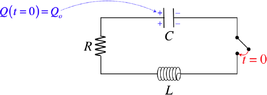
To get to this result, we (as usual) start with Kirchhoff's loop rule. This time the solution to differential equation has different characteristics, depending upon the values of the constants involved. For example, if the resistance is above a certain amount, the current dissipates before the charge is able to switch plates on the capacitor – it just decays directly down to zero. This is called an overdamped system. If the resistance is just barely large enough to cause this behavior, the system is said to be critically-damped . And if the resistance is low enough to allow oscillation, it is called under-damped . In this case, the charge does oscillate between the two capacitor plates, filling them a little less with every iteration.
Figure 5.4.5 – Current Behavior Based on Circuit Details
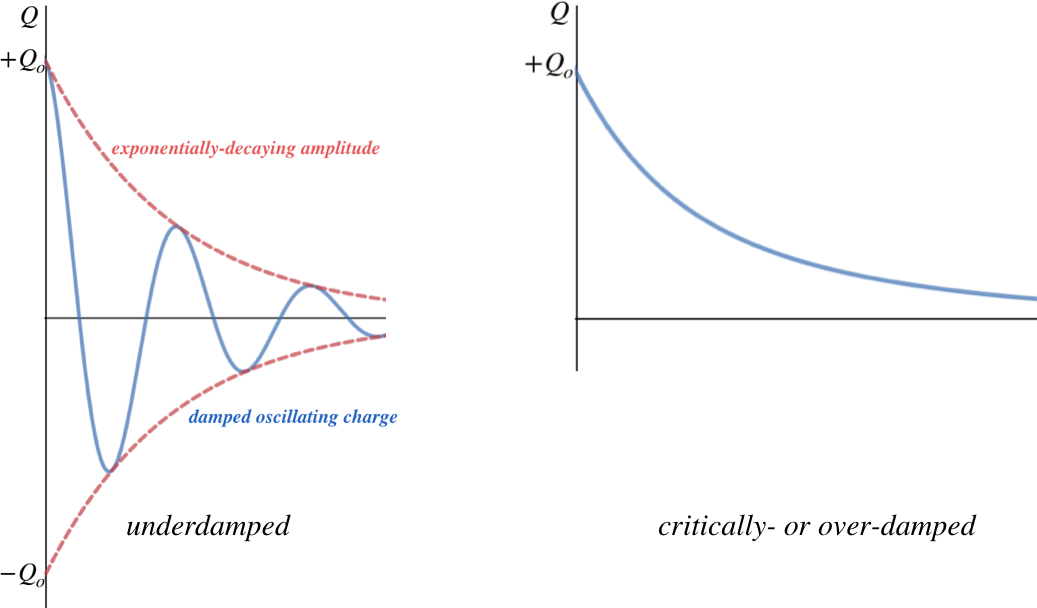
The critical criterion for determining which of these occurs is a comparison of \(R^2\) and \(\dfrac{4L}{C}\):
\[\begin{array}{l} \text{underdamped:} && R^2<\dfrac{4L}{C} \\ \text{critically-damped:} && R^2=\dfrac{4L}{C} \\ \text{overdamped:} && R^2>\dfrac{4L}{C} \end{array}\]

- school Campus Bookshelves
- menu_book Bookshelves
- perm_media Learning Objects
- login Login
- how_to_reg Request Instructor Account
- hub Instructor Commons
- Download Page (PDF)
- Download Full Book (PDF)
- Periodic Table
- Physics Constants
- Scientific Calculator
- Reference & Cite
- Tools expand_more
- Readability
selected template will load here
This action is not available.

9.2: Inductance and Inductors
- Last updated
- Save as PDF
- Page ID 25148

- James M. Fiore
- Mohawk Valley Community College
To begin, we need to examine the interrelation between electric current and magnetic fields in a conductor. When a current passes through a conductor, such as a wire, a magnetic field is created around the conductor that is proportional to the strength of the current. This is illustrated in Figure 9.2.1 .
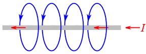
Figure 9.2.1 : Magnetic field around a conductor.
The magnetic field can be thought of as sets of concentric rings around the conductor, although for clarity only single loops are drawn in the Figure. The number of magnetic lines in a given area is known as the magnetic flux and is given the symbol \(\Phi\) (the Greek letter phi). The unit of magnetic flux is the weber, Wb, named after Wilhelm Weber, a 19th century German physicist.
\[\text{Magnetic flux } \equiv \text{ the number of magnetic lines enclosed in a given area.} \label{9.1} \]
Note that the magnetic field runs the length of the conductor. The direction of the field lines follows the right hand rule: if you grasp the wire with your right hand such that your thumb is pointing in the direction of conventional current flow, then your fingers wrap in the direction of the magnetic field. This rule is illustrated in Figure 9.2.2 .

Figure 9.2.2 : Right hand rule. Image source (modified)
If we form the conductor into a loop, the field lines are corralled into the center of the loop. This is illustrated in Figure 9.2.3 . In this diagram it can be seen that the lines effectively collect in the center, going into the page.
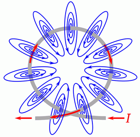
Figure 9.2.3 : Magnetic field around a loop.
The enhancement effect can be magnified by adding more loops in tandem. This is known as a solenoid and is shown in Figure 9.2.4 . It is the most basic form of an inductor.

Figure 9.2.4 : Solenoid.
The concentrating effect of the magnetic field is shown in Figure 9.2.5 . In this figure, the coil is shown from the side, as a cross-section of the individual loops. The dots inside the conductors indicate that the current is flowing toward you, out of the page; while the the crosses indicate that the current is flowing into the page. The lines of flux exit out the right, loop around, and reenter from the left. Due to limited space, the entire loop for each line is not drawn, and it is important to remember that magnetic flux lines do not end, but always create a loop. Further, although it is shown as a plane here, this field is three dimensional, with lines looping back into the page as well as in front of it.
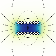
Figure 9.2.5 : Magnetic field in a solenoid. Image source
This is how electromagnets can be created 1 . The north pole is the exiting end (right side) of Figure 9.2.5 while the south pole is the entering end (left side).
If the current changes, there will be a commensurate change in the magnetic field. Further, this change in the field will induce a current in the conductor that creates a magnetic field that opposes the original change in the field. This is known as Lenz's law. Alternately, it can be stated that the induced current caused by a changing magnetic field will oppose the change in the original current that created that change in the original magnetic field.
At this point we can offer a proper definition of the weber:
\[1 \text{ weber } \equiv \text{ the magnetic flux that, acting on a single loop of a conductor, produces a potential of 1 volt if the flux is reduced to zero at an even rate over 1 second.} \label{9.2} \]
In magnetic circuits we are also interested in the magnetic flux density which is the magnetic flux per unit area. The symbol for flux density is \(B\) and has units of teslas (T), named after Nicola Tesla, the Serbo-Croatian-American engineer and inventor. One tesla is defined as one weber per square meter.
\[1 \text{ tesla } \equiv 1 \text{ weber} / \text{meter}^2 \label{9.3} \]
To provide a reference, the magnetic flux density of the Earth near the equator is approximately 31 \(\mu\)T, while the value of the voice coil gap in a loudspeaker is around 1 to 2 T, with medical MRI scanners being a little higher still.
Finally, we come to the definition of inductance and its unit, the henry:
\[\text{Inductance is a measure of the tendency of a conductor to oppose a change in the current flowing through it.} \label{9.4} \]
\[1 \text{ henry } \equiv 1 \text{ weber} / 1 \text{ amp} \label{9.5} \]
Unsurprisingly, the energy stored in the magnetic field of an inductor is proportional to the inductance. It is also proportional to the square of the current through the inductor.
\[W = \frac{1}{2} L I^2 \label{9.6} \]
\(W\) is the energy in joules,
\(L\) is the inductance in henries,
\(I\) is the current in amps.

Figure 9.2.6 : Simple air-core inductor dimensions.
An inductor in its simplest form consists of a series of wire loops. These might be wound around an iron core, although a non-ferrous core might also be used. For a simple single layer inductor, such as the one drawn in Figure 9.2.6 , the inductance is described by the following formula:
\[L=\mu \frac{A N^2}{l} \label{9.7} \]
\(\mu\) is the permeability of the core material,
\(A\) is the cross sectional area of the coil,
\(N\) is the number of coils or turns,
\(l\) is the length of the coil.
Inductors may also be wound using multiple layers or around a toroidal core, and these designs utilize alternate formulas.
Inductor Styles and Packaging
Equation \ref{9.7} indicates that, in order to achieve high inductance, we would like a core with high permeability, permeability being a measure of how easy it is to establish magnetic flux in said material. Substances such as iron or ferrite have a much greater permeability than air and are used commonly for cores. They do have a disadvantage in that they will saturate sooner than an air core, and this can lead to distortion.

Figure 9.2.7 : Electric bass guitar pickup.
Another approach is to pack as many turns as is possible within a given length. One way to do this is to minimize the thickness of the insulation around the wire 2 . This can be achieved by using a thin enamel coating instead of the typical plastic insulation. A second method is to use a very fine wire. This leads to two problems, namely an undesirable increase in equivalent series resistance (known colloquially as coil resistance or \(R_{coil}\)), and limited current carrying capacity. All of these effects have to be balanced in order to achieve the best performance for a given application.
Commercial inductors range in value from a fraction of a nanohenry for small surface mount “chip” inductors up to several henries. Some devices exhibit large internal inductances even though they are not specifically used as inductors. One common example is a transformer. Another example is an electric guitar or bass pickup, such as the one shown in Figure 9.2.7 with its cover removed. Units such as this may be constructed of several thousand turns of very fine wire (typically AWG 41 to 44) and achieve inductances in excess of one henry.
A variety of inductors is shown in Figure 9.2.9 , all of which are of the through-hole type (surface mount inductors do not appear considerably different from their surface mount resistor and capacitor cousins).
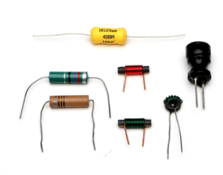
Figure 9.2.9 : A collection of inductors.
The two units toward the left are molded inductors and use a standard color code, similar to the ones used for resistors and capacitors. The unit at the top (yellow) is a high current inductor that features low \(R_{coil}\). The three inductors in the center use obvious ferrite cores, two wound on straight cores and the third wound on a toroidal core. The unit to the right uses a high permeability material at the very top and is wrapped in a plastic sheath for protection. Variable inductors are also a possibility and can be made by using a ferrite core that can be slid within the coils, effectively changing the permeability of the core (part ferrite, part air).

Figure 9.2.10 : Inductor schematic symbols (top-bottom): standard, variable, iron/ferrite core.
The schematic symbols for inductors are shown in Figure 9.2.10 . The standard symbol is at the top. The variable inductor symbol is in the middle and is a twolead device, somewhat reminiscent of the symbol for a rheostat. At the bottom is the symbol for an inductor with an iron, ferrite, or similar high permeability core. In general, like resistors, single inductors are not polarized and cannot be inserted into a circuit backwards. There are, however, special applications where multiple coils can be wound on a common core, and for these, the polarity of their interconnection can make a difference.
Inductor Data Sheet
A portion of an inductor data sheet is shown in Figure 9.2.12 . This page lists the available sizes of this particular model, each with corresponding quantities. We can see this model is available in inductance values ranging from 1 \(\mu\)H up to 100 mH. Tolerance of the smaller values is \(\pm\)10% while values at and above 33 \(\mu\)H are at \(\pm\)5%. \(Q\) is the quality factor and is particularly important in AC circuits (higher being better), along with its associated frequency, \(f_Q\). Continuing across we find \(I_R\). This is the maximum rated current. For the smaller values, we find they can withstand in excess of 2 amps while the larger units can withstand only tens of milliamps.
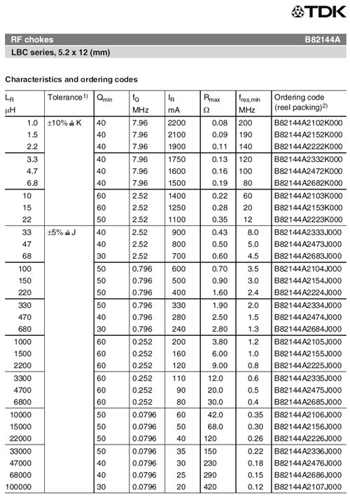
Figure 9.2.12 : Inductor data sheet. Courtesy of TDK
Finally, we come to \(R_{max}\). This is also known as \(R_{coil}\). It represents the equivalent series resistance of the inductor. In general, smaller is better. For this model, it ranges from a fraction of an ohm to a few hundred ohms. This trend is typical of inductors; all else being equal, the larger the inductance, the larger the value of the associated series resistance. In many circuits, the value of \(R_{coil}\) cannot be ignored.
Inductors in Series and in Parallel
Suppose we take two identical inductors and place them in series. This effectively doubles both the length and the number of loops. From Equation \ref{9.7} we can see that doubling both the number of loops and the length would double the inductance. This is because \(N^2\) goes up by a factor of four which is then halved be the increased length. Consequently, inductors in series add values just like resistors in series. By extension, inductors in parallel behave like resistors in parallel. The equivalent of parallel inductors can be found by using either the product-sum rule or by taking the reciprocal of the sum of their reciprocals.
Example 9.2.1
Find the equivalent inductance of the network shown in Figure 9.2.11 .
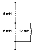
Figure 9.2.11 : Circuit for Example 9.2.1 .
The 6 mH and 12 mH inductors are in parallel. The equivalent value of the pair is:
\[L_{parallel} = \frac{L_2 L_3}{L_2+L_3} \nonumber \]
\[L_{parallel} = \frac{6 mH12 mH}{6 mH+12 mH} \nonumber \]
\[L_{parallel} = 4mH \nonumber \]
This combination is in series with the 5 mH inductor. Therefore the total equivalent inductance is 4 mH + 5 mH, or 9 mH.
Current-Voltage Relationship
The fundamental current-voltage relationship of the inductor is the mirror image of that of the capacitor:
\[\mathcal{v} = L \frac{di}{dt} \label{9.8} \]
This states that the voltage across the inductor is a function of how quickly the current is changing. If the current is not changing (i.e., in steady-state), then the voltage across the inductor is zero. In this case, the inductor behaves like a short, or more accurately, like its \(R_{coil}\) value. In contrast, during a rapid initial current change, the inductor voltage can be large, and thus the inductor behaves like an open.
If we rearrange Equation \ref{9.8} and solve for the rate of change of current, we find that:
\[\frac{di}{dt} = \frac{\mathcal{v}}{L} \label{9.9} \]
Thus if an inductor is fed by a constant voltage source, the current will rise at a constant rate equal to \(\mathcal{v}/L\). For example, considering the circuit in Figure 9.2.11 , we see a voltage source feeding a single inductor. If we were to plot the inductor's current over time, we would see something like the graph of Figure 9.2.12 .
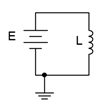
Figure 9.2.11 : Inductor with voltage source.
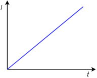
Figure 9.2.12 : Inductor current versus time.
As time progresses, the current through the inductor increases, flowing from top to bottom. With a theoretically perfect inductor and source, this would continue as long as the circuit was energized. In reality, this line would either begin to deflect horizontally as the source reached its limits, or the inductor would fail once its maximum current or power handling was reached. The slope of this line is dictated by the size of the applied voltage source and the inductance.
Example 9.2.2
Determine the rate of change of current through the inductor in the circuit of Figure 9.2.13 . Also determine the inductor's current 10 microseconds after power is switched on.
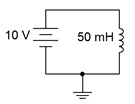
Figure 9.2.13 : Circuit for Example 9.2.2 .
From Equation \ref{9.9}, the rate of change of current is:
\[\frac{di}{dt} = \frac{\mathcal{v}}{L} \nonumber \]
\[\frac{di}{dt} = \frac{10V}{50 mH} \nonumber \]
\[\frac{di}{dt} = 200 A \text{ per second} \nonumber \]
In other words, for every second, the current rises another 200 amps. Thus, after just 10 microseconds it will have risen to 200 A/s times 10 \(\mu\)s, or 2 mA.
Equation \ref{9.8} is key to understanding the behavior of inductors. As noted previously, if an inductor is driven by a fixed voltage source and ignoring \(R_{coil}\), the current through it rises at the constant rate of \(\mathcal{v}/L\). This change in current through the inductor is not limitless. An instantaneous change requires that \(di/dt\) is infinite, and thus, the voltage driving the inductor would also have to be infinite, which is a clear impossibility. Therefore we can state a particularly important characteristic of capacitors:
\[\text{The current through an inductor cannot change instantaneously.} \label{9.10} \]
This observation will be central to analyzing the operation of inductors in DC circuits.
1 Truly one of the coolest inventions of all time: a magnet with an on/off switch.
2 The wound wire must be insulated otherwise each loop will short to the loops next to it and we'd be left with a tube instead of a series of loops.
- Ch1: Basic Concepts of Electricity
- Ch 2: Ohm’s Law
- Ch 3: Electrical Safety
- Ch 4: Scientific Notation and Metric Prefixes
- Ch 5: Series and Parallel Circuits
- Ch 6: Kirchoff’s Laws
- Ch 7: Series-Parallel Circuits
- Ch 8: Metering Circuits
- Ch 9: Electrical Instrumentation Signals
- Ch 10: DC Network Analysis
- Ch 11: Batteries and Power Systems
- Ch 12: Conductors and Insulators
- Ch 13: Capacitors
- Ch 14: Magnetism and Electromagnetism
- Ch 15: Inductors
- Ch 16: RC and L/R Time Constants
- AC Chapter 1: Basic AC Theory
- AC Chapter 2: Complex Numbers
- AC Chapter 3: Resistors in AC Circuits
- AC Chapter 4: Inductive Reactance and Impedance
- AC Chapter 5: Capacitive Reactance and Impedance
- AC Chapter 6: Reactance and Impedance – R, L, and C
- AC Chapter 7: Resonance
- AC Chapter 8: Mixed Frequency AC Signals
- AC Chapter 9: Filters
- AC Chapter 10: Transformers
- Introduction to Communication Systems
- The Electromagnetic Spectrum
- Intro to Signals
- Intro to Systems
- Digital Electronics
- Electronic Circuits and Devices
- Op Amps Ch 1: Introduction to Op Amps
- Op Amps Ch 2: Common Op Amp Configurations
- Video Library
- Support ElectronX
Practice Problems: Inductors in AC Circuits
Difficult concepts.
These are some concepts that new learners often find challenging. It is probably worthwhile to read through these concepts because they may explain challenges you are facing while learning about inductors in AC circuits.
Resistance vs. Reactance vs. Impedance
These three terms represent different forms of opposition to electric current. Despite the fact that they are measured in the same unit (ohms: Omega ), they are not the same. Resistance is best thought of as electrical friction, whereas reactance is best thought of as electrical inertia. Whereas resistance creates a voltage drop by dissipating energy, reactance creates a voltage drop by storing and releasing energy. Impedance is a term encompassing both resistance and reactance, usually a combination of both.
Phasors, used to represent AC amplitude and phase relations.
A powerful tool used for understanding the operation of AC circuits is the phasor diagram, consisting of arrows pointing in different directions: the length of each arrow representing the amplitude of some AC quantity (voltage, current, or impedance), and the angle of each arrow representing the shift in phase relative to the other arrows. By representing each AC quantity thusly, we may more easily calculate their relationships to one another, with the phasors showing us how to apply trigonometry (Pythagorean Theorem, sine, cosine, and tangent functions) to the various calculations. An analytical parallel to the graphic tool of phasor diagrams is complex numbers, where we represent each phasor (arrow) by a pair of numbers: either a magnitude and angle (polar notation), or by “real” and “imaginary” magnitudes (rectangular notation). Where phasor diagrams are helpful is in applications where their respective AC quantities add: the resultant of two or more phasors stacked tip-to-tail being the mathematical sum of the phasors. Complex numbers, on the other hand, may be added, subtracted, multiplied, and divided; the last two operations being difficult to graphically represent with arrows.
Conductance, Susceptance, and Admittance.
Conductance, symbolized by the letter G, is the mathematical reciprocal of resistance ( 1 \over R ). Students typically encounter this quantity in their DC studies and quickly ignore it. In AC calculations, however, conductance and its AC counterparts (susceptance, the reciprocal of reactance B = {1 \over X} and admittance, the reciprocal of impedance Y = {1 \over Z} ) are very necessary in order to draw phasor diagrams for parallel networks.
Question 1. (Click on arrow for answer)
As a general rule, inductors oppose change in ( choose: voltage or current ), and they do so by . . . (complete the sentence).
Based on this rule, determine how an inductor would react to a constant AC current that increases in frequency. Would an inductor drop more or less voltage, given a greater frequency? Explain your answer.
File Num: 00578
As a general rule, inductors oppose change in current , and they do so by producing a voltage.
An inductor will drop a greater amount of AC voltage, given the same AC current, at a greater frequency.
This question is an exercise in qualitative thinking: relating rates of change to other variables, without the use of numerical quantities. The general rule stated here is very, very important for students to master, and be able to apply to a variety of circumstances. If they learn nothing about inductors except for this rule, they will be able to grasp the function of a great many inductor circuits.
Question 2. (Click on arrow for answer)
\int f(x) dx Calculus alert!
We know that the formula relating instantaneous voltage and current in an inductor is this:
Knowing this, determine at what points on this sine wave plot for inductor current is the inductor voltage equal to zero, and where the voltage is at its positive and negative peaks. Then, connect these points to draw the waveform for inductor voltage:

How much phase shift (in degrees) is there between the voltage and current waveforms? Which waveform is leading and which waveform is lagging?
File Num: 00576

For an inductor, voltage is leading and current is lagging, by a phase shift of 90 ^{o} .
This question is an excellent application of the calculus concept of the derivative : relating one function (instantaneous voltage, e ) with the instantaneous rate-of-change of another function (current, di \over dt ).
Question 3. (Click on arrow for answer)
Calculate the total impedance offered by these two inductors to a sinusoidal signal with a frequency of 60 Hz:

Show your work using two different problem-solving strategies:
- Calculating total inductance ( L_{total} ) first, then total impedance ( Z_{total} ).
- Calculating individual impedances first ( Z_{L1} and Z_{L2} ), then total impedance ( Z_{total} ).
Do these two strategies yield the same total impedance value? Why or why not?
File Num: 01832
Follow-up question: draw a phasor diagram showing how the two inductors’ impedance phasors geometrically add to equal the total impedance.
The purpose of this question is to get students to realize that any way they can calculate total impedance is correct, whether calculating total inductance and then calculating impedance from that, or by calculating the impedance of each inductor and then combining impedances to find a total impedance. This should be reassuring, because it means students have a way to check their work when analyzing circuits such as this!
Question 4. (Click on arrow for answer)
Write an equation that solves for the impedance of this series circuit. The equation need not solve for the phase angle between voltage and current, but merely provide a scalar figure for impedance (in ohms):

File Num: 01844
Ask your students if this equation looks similar to any other mathematical equations they’ve seen before. If not, square both sides of the equation so it looks like Z^2 = R^2 + X^2 and ask them again.
Question 5. (Click on arrow for answer)
Calculate the total impedance of this LR circuit, once using nothing but scalar numbers, and again using complex numbers:

File Num: 01837
Some electronics textbooks (and courses) tend to emphasize scalar impedance calculations, while others emphasize complex number calculations. While complex number calculations provide more informative results (a phase shift given in every variable!) and exhibit conceptual continuity with DC circuit analysis (same rules, similar formulae), the scalar approach lends itself better to conditions where students do not have access to calculators capable of performing complex number arithmetic. Yes, of course, you can do complex number arithmetic without a powerful calculator, but it’s a lot more tedious and prone to errors than calculating with admittances, susceptances, and conductances (primarily because the phase shift angle is omitted for each of the variables).
Question 6. (Click on arrow for answer)
Calculate the total impedance offered by these two inductors to a sinusoidal signal with a frequency of 120 Hz:

Show your work using three different problem-solving strategies:
- Calculating individual admittances first ( Y_{L1} and Y_{L2} ), then total admittance ( Y_{total} ), then total impedance ( Z_{total} ).
- Using complex numbers: calculating individual impedances first ( Z_{L1} and Z_{L2} ), then total impedance ( Z_{total} ).
File Num: 01833
Follow-up question: draw a phasor diagram showing how the two inductors’ admittance phasors geometrically add to equal the total admittance.
Question 7. (Click on arrow for answer)
Does an inductor’s opposition to alternating current increase or decrease as the frequency of that current increases? Also, explain why we refer to this opposition of AC current in an inductor as reactance instead of resistance .
File Num: 00580
The opposition to AC current (“reactance”) of an inductor increases as frequency increases. We refer to this opposition as “reactance” rather than “resistance” because it is non-dissipative in nature. In other words, reactance causes no power to leave the circuit.
Ask your students to define the relationship between inductor reactance and frequency as either “directly proportional” or “inversely proportional”. These are two phrases used often in science and engineering to describe whether one quantity increases or decreases as another quantity increases. Your students definitely need to be familiar with both these phrases, and be able to interpret and use them in their technical discussions.
Also, discuss the meaning of the word “non-dissipative” in this context. How could we prove that the opposition to current expressed by an inductor is non-dissipative? What would be the ultimate test of this?
Question 8. (Click on arrow for answer)
What will happen to the brightness of the light bulb as the iron core is moved away from the wire coil in this circuit? Explain why this happens.

File Num: 00095
The light bulb will glow brighter when the iron core is moved away from the wire coil, due to the change in inductive reactance (X _{L} ).
Follow-up question: what circuit failure(s) could cause the light bulb to glow brighter than it should?
One direction you might want to lead your students in with this question is how AC power may be controlled using this principle. Controlling AC power with a variable reactance has a definite advantage over controlling AC power with a variable resistance : less wasted energy in the form of heat.
Question 9. (Click on arrow for answer)
An inductor rated at 4 Henrys is subjected to a sinusoidal AC voltage of 24 volts RMS, at a frequency of 60 hertz. Write the formula for calculating inductive reactance ( X_L ), and solve for current through the inductor.
File Num: 00582
The current through this inductor is 15.92 mA RMS.
I have consistently found that qualitative (greater than, less than, or equal) analysis is much more difficult for students to perform than quantitative (punch the numbers on a calculator) analysis. Yet, I have consistently found on the job that people lacking qualitative skills make more “silly” quantitative errors because they cannot validate their calculations by estimation.
In light of this, I always challenge my students to qualitatively analyze formulae when they are first introduced to them. Ask your students to identify what will happen to one term of an equation if another term were to either increase, or decrease (you choose the direction of change). Use up and down arrow symbols if necessary to communicate these changes graphically. Your students will greatly benefit in their conceptual understanding of applied mathematics from this kind of practice!
Question 10. (Click on arrow for answer)
At what frequency does a 350 mH inductor have 4.7 k \Omega of reactance? Write the formula for solving this, in addition to calculating the frequency.
File Num: 00586
Be sure to ask your students to demonstrate the algebraic manipulation of the original formula, in providing the answer to this question. Algebraic manipulation of equations is a very important skill to have, and it comes only by study and practice.
Question 11. (Click on arrow for answer)
How much inductance would an inductor have to possess in order to provide 540 \Omega of reactance at a frequency of 400 Hz? Write the formula for solving this, in addition to calculating the frequency.
File Num: 03277
Question 12. (Click on arrow for answer)
Explain all the steps necessary to calculate the amount of current in this inductive AC circuit:

File Num: 01552
The current is not difficult to calculate, so obviously the most important aspect of this question is not the math. Rather, it is the procedure of calculation: what to do first, second, third, etc., in obtaining the final answer.
Question 13. (Click on arrow for answer)
In this AC circuit, the resistor offers 300 \Omega of resistance, and the inductor offers 400 \Omega of reactance. Together, their series opposition to alternating current results in a current of 10 mA from the 5 volt source:

How many ohms of opposition does the series combination of resistor and inductor offer? What name do we give to this quantity, and how do we symbolize it, being that it is composed of both resistance ( R ) and reactance ( X )?
File Num: 00584
Follow-up question: suppose that the inductor suffers a failure in its wire winding, causing it to “open.” Explain what effect this would have on circuit current and voltage drops.
Students may experience difficulty arriving at the same quantity for impedance shown in the answer. If this is the case, help them problem-solve by suggesting they simplify the problem : short past one of the load components and calculate the new circuit current. Soon they will understand the relationship between total circuit opposition and total circuit current, and be able to apply this concept to the original problem.
Ask your students why the quantities of 300 \Omega and 400 \Omega do not add up to 700 \Omega like they would if they were both resistors. Does this scenario remind them of another mathematical problem where 3 + 4 = 5 ? Where have we seen this before, especially in the context of electric circuits?
Once your students make the cognitive connection to trigonometry, ask them the significance of these numbers’ addition. Is it enough that we say a component has an opposition to AC of 400 \Omega , or is there more to this quantity than a single, scalar value? What type of number would be suitable for representing such a quantity, and how might it be written?
Question 14. (Click on arrow for answer)
While studying DC circuit theory, you learned that resistance was an expression of a component’s opposition to electric current. Then, when studying AC circuit theory, you learned that reactance was another type of opposition to current. Now, a third term is introduced: impedance . Like resistance and reactance, impedance is also a form of opposition to electric current.
Explain the difference between these three quantities (resistance, reactance, and impedance) using your own words.
File Num: 01567
The fundamental distinction between these terms is one of abstraction: impedance is the most general term, encompassing both resistance and reactance . Here is an explanation given in terms of logical sets (using a Venn diagram ), along with an analogy from animal taxonomy:

Resistance is a type of impedance, and so is reactance. The difference between the two has to do with energy exchange .
The given answer is far from complete. I’ve shown the semantic relationship between the terms resistance, reactance, and impedance, but I have only hinted at the conceptual distinctions between them. Be sure to discuss with your students what the fundamental difference is between resistance and reactance, in terms of electrical energy exchange.
Question 15. (Click on arrow for answer)
In DC circuits, we have Ohm’s Law to relate voltage, current, and resistance together:
In AC circuits, we similarly need a formula to relate voltage, current, and impedance together. Write three equations, one solving for each of these three variables: a set of Ohm’s Law formulae for AC circuits. Be prepared to show how you may use algebra to manipulate one of these equations into the other two forms.
File Num: 00590
If using phasor quantities (complex numbers) for voltage, current, and impedance, the proper way to write these equations is as follows:
Bold-faced type is a common way of denoting vector quantities in mathematics.
Although the use of phasor quantities for voltage, current, and impedance in the AC form of Ohm’s Law yields certain distinct advantages over scalar calculations, this does not mean one cannot use scalar quantities. Often it is appropriate to express an AC voltage, current, or impedance as a simple scalar number.
Question 16. (Click on arrow for answer)
It is often necessary to represent AC circuit quantities as complex numbers rather than as scalar numbers, because both magnitude and phase angle are necessary to consider in certain calculations.
When representing AC voltages and currents in polar form, the angle given refers to the phase shift between the given voltage or current, and a “reference” voltage or current at the same frequency somewhere else in the circuit. So, a voltage of 3.5 \hbox{ V} \angle -45^o means a voltage of 3.5 volts magnitude, phase-shifted 45 degrees behind (lagging) the reference voltage (or current), which is defined to be at an angle of 0 degrees.
But what about impedance (Z) ? Does impedance have a phase angle, too, or is it a simple scalar number like resistance or reactance?
Calculate the amount of current that would go through a 100 mH inductor with 36 volts RMS applied to it at a frequency of 400 Hz. Then, based on Ohm’s Law for AC circuits and what you know of the phase relationship between voltage and current for an inductor, calculate the impedance of this inductor in polar form . Does a definite angle emerge from this calculation for the inductor’s impedance? Explain why or why not.
File Num: 00588
This is a challenging question, because it asks the student to defend the application of phase angles to a type of quantity that does not really possess a wave-shape like AC voltages and currents do. Conceptually, this is difficult to grasp. However, the answer is quite clear through the Ohm’s Law calculation ( Z = {E \over I} ).
Although it is natural to assign a phase angle of 0 ^{o} to the 36 volt supply, making it the reference waveform, this is not actually necessary. Work through this calculation with your students, assuming different angles for the voltage in each instance. You should find that the impedance computes to be the same exact quantity every time.
Question 17. (Click on arrow for answer)
Determine the input frequency necessary to give the output voltage a phase shift of 75 ^{o} :

Also, write an equation that solves for frequency ( f ), given all the other variables ( R , L , and phase angle \theta ).
File Num: 03282
Discuss with your students what a good procedure might be for calculating the unknown values in this problem, and also how they might check their work.
Students often have difficulty formulating a method of solution: determining what steps to take to get from the given conditions to a final answer. While it is helpful at first for you (the instructor) to show them, it is bad for you to show them too often, lest they stop thinking for themselves and merely follow your lead. A teaching technique I have found very helpful is to have students come up to the board (alone or in teams) in front of class to write their problem-solving strategies for all the others to see. They don’t have to actually do the math, but rather outline the steps they would take, in the order they would take them.
By having students outline their problem-solving strategies , everyone gets an opportunity to see multiple methods of solution, and you (the instructor) get to see how (and if!) your students are thinking. An especially good point to emphasize in these “open thinking” activities is how to check your work to see if any mistakes were made.
Question 18. (Click on arrow for answer)
Determine the necessary resistor value to give the output voltage a phase shift of 44 ^{o} :

Also, write an equation that solves for this resistance value ( R ), given all the other variables ( f , L , and phase angle \theta ).
File Num: 03283
Question 19. (Click on arrow for answer)
Determine the input frequency necessary to give the output voltage a phase shift of -40 ^{o} :

File Num: 03280
Question 20. (Click on arrow for answer)
Determine the necessary resistor value to give the output voltage a phase shift of -60 ^{o} :

File Num: 03281
Question 21. (Click on arrow for answer)
If a sinusoidal voltage is applied to an impedance with a phase angle of 0 ^{o} , the resulting voltage and current waveforms will look like this:

Given that power is the product of voltage and current ( p = i e ), plot the waveform for power in this circuit.
File Num: 00631

Ask your students to observe the waveform shown in the answer closely, and determine what sign the power values always are. Note how the voltage and current waveforms alternate between positive and negative, but power does not. Of what significance is this to us? What does this indicate about the nature of a load with an impedance phase angle of 0 ^{o} ?
Question 22. (Click on arrow for answer)
If a sinusoidal voltage is applied to an impedance with a phase angle of 90 ^{o} , the resulting voltage and current waveforms will look like this:

Given that power is the product of voltage and current ( p = i e ), plot the waveform for power in this circuit. Also, explain how the mnemonic phrase “ELI the ICE man” applies to these waveforms.
File Num: 00632

The mnemonic phrase, “ELI the ICE man” indicates that this phase shift is due to an inductance rather than a capacitance.
Ask your students to observe the waveform shown in the answer closely, and determine what sign the power values are. Note how the power waveform alternates between positive and negative values, just as the voltage and current waveforms do. Ask your students to explain what negative power could possibly mean.
Of what significance is this to us? What does this indicate about the nature of a load with an impedance phase angle of 90 ^{o} ?
The phrase, “ELI the ICE man” has been used be generations of technicians to remember the phase relationships between voltage and current for inductors and capacitors, respectively. One area of trouble I’ve noted with students, though, is being able to interpret which waveform is leading and which one is lagging, from a time-domain plot such as this.
Question 23. (Click on arrow for answer)
The impedance triangle is often used to graphically relate Z , R , and X in a series circuit:

Unfortunately, many students do not grasp the significance of this triangle, but rather memorize it as a “trick” used to calculate one of the three variables given the other two. Explain why a right triangle is an appropriate form to relate these variables, and what each side of the triangle actually represents.
File Num: 02076
Each side of the impedance triangle is actually a phasor (a vector representing impedance with magnitude and direction):

Since the phasor for resistive impedance ( Z_R ) has an angle of zero degrees and the phasor for reactive impedance ( Z_C or Z_L ) either has an angle of +90 or -90 degrees, the phasor sum representing total series impedance will form the hypotenuse of a right triangle when the first to phasors are added (tip-to-tail).
Follow-up question: as a review, explain why resistive impedance phasors always have an angle of zero degrees, and why reactive impedance phasors always have angles of either +90 degrees or -90 degrees.
The question is sufficiently open-ended that many students may not realize exactly what is being asked until they read the answer. This is okay, as it is difficult to phrase the question in a more specific manner without giving away the answer!
Question 24. (Click on arrow for answer)
Use the “impedance triangle” to calculate the impedance of this series combination of resistance ( R ) and inductive reactance ( X ):

Explain what equation(s) you use to calculate Z .
File Num: 02081
Be sure to have students show you the form of the Pythagorean Theorem, rather than showing them yourself, since it is so easy for students to research on their own.
Question 25. (Click on arrow for answer)
Use the “impedance triangle” to calculate the necessary reactance of this series combination of resistance ( R ) and inductive reactance ( X ) to produce the desired total impedance of 145 \Omega :

Explain what equation(s) you use to calculate X , and the algebra necessary to achieve this result from a more common formula.
File Num: 02083
Question 26. (Click on arrow for answer)

Identify which trigonometric functions (sine, cosine, or tangent) are represented by each of the following ratios, with reference to the angle labeled with the Greek letter “Theta” ( \Theta ):
File Num: 02084
Ask your students to explain what the words “hypotenuse”, “opposite”, and “adjacent” refer to in a right triangle.
Question 27. (Click on arrow for answer)
Trigonometric functions such as sine , cosine , and tangent are useful for determining the ratio of right-triangle side lengths given the value of an angle. However, they are not very useful for doing the reverse: calculating an angle given the lengths of two sides.

Suppose we wished to know the value of angle \Theta , and we happened to know the values of Z and R in this impedance triangle. We could write the following equation, but in its present form we could not solve for \Theta :
The only way we can algebraically isolate the angle \Theta in this equation is if we have some way to “undo” the cosine function. Once we know what function will “undo” cosine, we can apply it to both sides of the equation and have \Theta by itself on the left-hand side.
There is a class of trigonometric functions known as inverse or “arc” functions which will do just that: “undo” a regular trigonometric function so as to leave the angle by itself. Explain how we could apply an “arc-function” to the equation shown above to isolate \Theta .
File Num: 02086
I like to show the purpose of trigonometric arcfunctions in this manner, using the cardinal rule of algebraic manipulation (do the same thing to both sides of an equation) that students are familiar with by now. This helps eliminate the mystery of arcfunctions for students new to trigonometry.
Question 28. (Click on arrow for answer)
A series AC circuit contains 1125 ohms of resistance and 1500 ohms of reactance for a total circuit impedance of 1875 ohms. This may be represented graphically in the form of an impedance triangle:

Since all side lengths on this triangle are known, there is no need to apply the Pythagorean Theorem. However, we may still calculate the two non-perpendicular angles in this triangle using “inverse” trigonometric functions, which are sometimes called arc functions.
Identify which arc-function should be used to calculate the angle \Theta given the following pairs of sides:
Show how three different trigonometric arcfunctions may be used to calculate the same angle \Theta .
File Num: 02085
Challenge question: identify three more arcfunctions which could be used to calculate the same angle \Theta .
Some hand calculators identify arc-trig functions by the letter “A” prepending each trigonometric abbreviation (e.g. “ASIN” or “ATAN”). Other hand calculators use the inverse function notation of a -1 exponent, which is not actually an exponent at all (e.g. \sin^{-1} or \tan^{-1} ). Be sure to discuss function notation on your students’ calculators, so they know what to invoke when solving problems such as this.
Question 29. (Click on arrow for answer)

File Num: 00850
Follow-up question: algebraically manipulate this equation to produce two more; one solving for R and the other solving for X .
Question 30. (Click on arrow for answer)
Draw a phasor diagram showing the trigonometric relationship between resistance, reactance, and impedance in this series circuit:

Show mathematically how the resistance and reactance combine in series to produce a total impedance (scalar quantities, all). Then, show how to analyze this same circuit using complex numbers: regarding component as having its own impedance, demonstrating mathematically how these impedances add up to comprise the total impedance (in both polar and rectangular forms).
File Num: 01827

I want students to see that there are two different ways of approaching a problem such as this: with scalar math and with complex number math. If students have access to calculators that can do complex-number arithmetic, the “complex” approach is actually simpler for series-parallel combination circuits, and it yields richer (more informative) results.
Ask your students to determine which of the approaches most resembles DC circuit calculations. Incidentally, this is why I tend to prefer complex-number AC circuit calculations over scalar calculations: because of the conceptual continuity between AC and DC. When you use complex numbers to represent AC voltages, currents, and impedances, almost all the rules of DC circuits still apply. The big exception, of course, is calculations involving power .
Question 31. (Click on arrow for answer)
Calculate the total impedance for these two 100 mH inductors at 2.3 kHz, and draw a phasor diagram showing circuit impedances ( Z_{total} , R , and X ):

Now, re-calculate impedance and re-draw the phasor impedance diagram supposing the second inductor is replaced by a 1.5 k \Omega resistor:

File Num: 02080

Phasor diagrams are powerful analytical tools, if one knows how to draw and interpret them. With hand calculators being so powerful and readily able to handle complex numbers in either polar or rectangular form, there is temptation to avoid phasor diagrams and let the calculator handle all the angle manipulation. However, students will have a much better understanding of phasors and complex numbers in AC circuits if you hold them accountable to representing quantities in that form.
Question 32. (Click on arrow for answer)
Calculate the total impedance of this series LR circuit and then calculate the total circuit current:

Also, draw a phasor diagram showing how the individual component impedances relate to the total impedance.
File Num: 02103
This would be an excellent question to have students present methods of solution for. Sometimes I have students present nothing but their solution steps on the board in front of class (no arithmetic at all), in order to generate a discussion on problem-solving strategies. The important part of their education here is not to arrive at the correct answer or to memorize an algorithm for solving this type of problem, but rather how to think like a problem-solver, and how to methodically apply the math they know to the problem(s) at hand.
Question 33. (Click on arrow for answer)
Calculate the magnitude and phase shift of the current through this inductor, taking into consideration its intrinsic winding resistance:

File Num: 00639
Inductors are the least “pure” of any reactive component, due to significant quantities of resistance in the windings. Discuss this fact with your students, and what it means with reference to choosing inductors versus capacitors in circuit designs that could use either.
Question 34. (Click on arrow for answer)
Solve for all voltages and currents in this series LR circuit:

File Num: 01830
Nothing special here — just a straightforward exercise in series AC circuit calculations.
Students often have difficulty formulating a method of solution: determining what steps to take to get from the given conditions to a final answer. While it is helpful at first for you (the instructor) to show them, it is bad for you to show them too often, lest they stop thinking for themselves and merely follow your lead. A teaching technique I have found very helpful is to have students come up to the board (alone or in teams) in front of class to write their problem-solving strategies for all the others to see. They don’t have to actually do the math, but rather outline the steps they would take, in the order they would take them. The following is a sample of a written problem-solving strategy for analyzing a series resistive-reactive AC circuit:
By having students outline their problem-solving strategies, everyone gets an opportunity to see multiple methods of solution, and you (the instructor) get to see how (and if!) your students are thinking. An especially good point to emphasize in these “open thinking” activities is how to check your work to see if any mistakes were made.
Question 35. (Click on arrow for answer)
Solve for all voltages and currents in this series LR circuit, and also calculate the phase angle of the total impedance:

File Num: 01831
Question 36. (Click on arrow for answer)
Determine the total current and all voltage drops in this circuit, stating your answers the way a multimeter would register them:

- L_1 = 250 \hbox{ mH}
- L_2 = 60 \hbox{ mH}
- R_1 = 6.8 \hbox{ k}\Omega
- R_2 = 1.2 \hbox{ k}\Omega
- V_{supply} = 13.4 \hbox{ V RMS}
- f_{supply} = 6.5 \hbox{ kHz}
Also, calculate the phase angle ( \Theta ) between voltage and current in this circuit, and explain where and how you would connect an oscilloscope to measure that phase shift.
File Num: 01841
- I_{total} = 0.895 \hbox{ mA}
- V_{L1} = 9.14 \hbox{ V}
- V_{L2} = 2.19 \hbox{ V}
- V_{R1} = 6.08 \hbox{ V}
- V_{R2} = 1.07 \hbox{ V}
- \Theta = 57.71^o
I suggest using a dual-trace oscilloscope to measure total voltage (across the supply terminals) and voltage drop across resistor R_2 . Theoretically, measuring the voltage dropped by either resistor would be fine, but R_2 works better for practical reasons (oscilloscope input lead grounding). Phase shift then could be measured either in the time domain or by a Lissajous figure analysis.
Some students many wonder what type of numerical result best corresponds to a multimeter’s readings, if they do their calculations using complex numbers (“do I use polar or rectangular form, and if rectangular do I use the real or the imaginary part?”). The answers given for this question should clarify that point.
It is very important that students know how to apply this knowledge of AC circuit analysis to real-world situations. Asking students to determine how they would connect an oscilloscope to the circuit to measure \Theta is an exercise in developing their abstraction abilities between calculations and actual circuit scenarios.
Question 37. (Click on arrow for answer)
One way to vary the amount of power delivered to a resistive AC load is by varying another resistance connected in series:

A problem with this power control strategy is that power is wasted in the series resistance ( I^2R_{series} ). A different strategy for controlling power is shown here, using a series inductance rather than resistance:

Explain why the latter circuit is more power-efficient than the former, and draw a phasor diagram showing how changes in L_{series} affect Z_{total} .
File Num: 01829
Inductors are reactive rather than resistive components, and therefore do not dissipate power (ideally).

Follow-up question: the inductive circuit is not just more energy-efficient — it is safer as well. Identify a potential safety hazard that the resistive power-control circuit poses due to the energy dissipation of its variable resistor.
If appropriate, you may want to mention devices called saturable reactors , which are used to control power in AC circuits by the exact same principle: varying a series inductance.
Question 38. (Click on arrow for answer)
A quantity sometimes used in DC circuits is conductance , symbolized by the letter G . Conductance is the reciprocal of resistance ( G = {1 \over R} ), and it is measured in the unit of siemens.
Expressing the values of resistors in terms of conductance instead of resistance has certain benefits in parallel circuits. Whereas resistances ( R ) add in series and “diminish” in parallel (with a somewhat complex equation), conductances ( G ) add in parallel and “diminish” in series. Thus, doing the math for series circuits is easier using resistance and doing math for parallel circuits is easier using conductance:

In AC circuits, we also have reciprocal quantities to reactance ( X ) and impedance ( Z ). The reciprocal of reactance is called susceptance ( B = {1 \over X} ), and the reciprocal of impedance is called admittance ( Y = {1 \over Z} ). Like conductance, both these reciprocal quantities are measured in units of siemens.
Write an equation that solves for the admittance ( Y ) of this parallel circuit. The equation need not solve for the phase angle between voltage and current, but merely provide a scalar figure for admittance (in siemens):

File Num: 00853
Follow-up question \#1: draw a phasor diagram showing how Y , G , and B relate.
Follow-up question \#2: re-write this equation using quantities of resistance ( R ), reactance ( X ), and impedance ( Z ), instead of conductance ( G ), susceptance ( B ), and admittance ( Y ).
Ask your students if this equation looks familiar to them. It should!
The answer to the second follow-up question is a matter of algebraic substitution. Work through this process with your students, and then ask them to compare the resulting equation with other equations they’ve seen before. Does its form look familiar to them in any way?
Question 39. (Click on arrow for answer)
Students studying AC electrical theory become familiar with the impedance triangle very soon in their studies:

What these students might not ordinarily discover is that this triangle is also useful for calculating electrical quantities other than impedance. The purpose of this question is to get you to discover some of the triangle’s other uses.
Fundamentally, this right triangle represents phasor addition , where two electrical quantities at right angles to each other (resistive versus reactive) are added together. In series AC circuits, it makes sense to use the impedance triangle to represent how resistance ( R ) and reactance ( X ) combine to form a total impedance ( Z ), since resistance and reactance are special forms of impedance themselves, and we know that impedances add in series.
List all of the electrical quantities you can think of that add (in series or in parallel) and then show how similar triangles may be drawn to relate those quantities together in AC circuits.
File Num: 02077
- Series impedances
- Series voltages
- Parallel admittances
- Parallel currents
- Power dissipations
I will show you one graphical example of how a triangle may relate to electrical quantities other than series impedances:

It is very important for students to understand that the triangle only works as an analysis tool when applied to quantities that add . Many times I have seen students try to apply the Z – R – X impedance triangle to parallel circuits and fail because parallel impedances do not add . The purpose of this question is to force students to think about where the triangle is applicable to AC circuit analysis, and not just to use it blindly.
The power triangle is an interesting application of trigonometry applied to electric circuits. You may not want to discuss power with your students in great detail if they are just beginning to study voltage and current in AC circuits, because power is a sufficiently confusing subject on its own.
Question 40. (Click on arrow for answer)
Explain why the “impedance triangle” is not proper to use for relating total impedance, resistance, and reactance in parallel circuits as it is for series circuits:

File Num: 02078
Impedances do not add in parallel.
Follow-up question: what kind of a triangle could be properly applied to a parallel AC circuit, and why?
Trying to apply the Z – R – X triangle directly to parallel AC circuits is a common mistake many new students make. Key to knowing when and how to use triangles to graphically depict AC quantities is understanding why the triangle works as an analysis tool and what its sides represent.
Question 41. (Click on arrow for answer)
Calculate the total impedance for these two 100 mH inductors at 2.3 kHz, and draw a phasor diagram showing circuit admittances ( Y_{total} , G , and B ):

Now, re-calculate impedance and re-draw the phasor admittance diagram supposing the second inductor is replaced by a 1.5 k \Omega resistor:

File Num: 02079

Challenge question: why are the susceptance vectors ( B_{L1} and B_{L2} ) pointed down instead of up as impedance vectors for inductances typically are?
Question 42. (Click on arrow for answer)
Calculate the individual currents through the inductor and through the resistor, the total current, and the total circuit impedance:

Also, draw a phasor diagram showing how the individual component currents relate to the total current.
File Num: 02104
Question 43. (Click on arrow for answer)
A large AC electric motor under load can be considered as a parallel combination of resistance and inductance:

Calculate the current necessary to power this motor if the equivalent resistance and inductance is 20 \Omega and 238 mH, respectively.
File Num: 01839
This is a practical example of a parallel LR circuit, as well as an example of how complex electrical devices may be “modeled” by collections of ideal components. To be honest, a loaded AC motor’s characteristics are quite a bit more complex than what the parallel LR model would suggest, but at least it’s a start!
Question 44. (Click on arrow for answer)

Calculate the equivalent inductance ( L_{eq} ) if the measured source current is 27.5 amps and the motor’s equivalent resistance ( R_{eq} ) is 11.2 \Omega .
File Num: 01840
Here is a case where scalar calculations (R, G, X, B, Y) are much easier than complex number calculations (all Z) would be.
Question 45. (Click on arrow for answer)
Determine the total current and all component currents in this circuit, stating your answers the way a multimeter would register them:

- L_1 = 1.2 \hbox{ H}
- L_2 = 650 \hbox{ mH}
- R_1 = 33 \hbox{ k}\Omega
- R_2 = 27 \hbox{ k}\Omega
- V_{supply} = 19.7 \hbox{ V RMS}
- f_{supply} = 4.5 \hbox{ kHz}
File Num: 01842
- I_{total} = 2.12 \hbox{ mA}
- I_{L1} = 581 \> \mu \hbox{A}
- I_{L2} = 1.07 \hbox{ mA}
- I_{R1} = 597 \> \mu \hbox{A}
- I_{R2} = 730 \> \mu \hbox{A}
- \Theta = 51.24^o
Measuring \Theta with an oscilloscope requires the addition of a shunt resistor into this circuit, because oscilloscopes are (normally) only able to measure voltage, and there is no phase shift between any voltages in this circuit because all components are in parallel. I leave it to you to suggest where to insert the shunt resistor, what resistance value to select for the task, and how to connect the oscilloscope to the modified circuit.
Question 46. (Click on arrow for answer)
Calculate the total impedances (complete with phase angles) for each of the following inductor-resistor circuits:

File Num: 02106

Have your students explain how they solved for each impedance, step by step. You may find different approaches to solving the same problem(s), and your students will benefit from seeing the diversity of solution techniques.
Question 47. (Click on arrow for answer)
A doorbell ringer has a solenoid with an inductance of 63 mH connected in parallel with a lamp (for visual indication) having a resistance of 150 ohms:

Calculate the phase shift of the total current (in units of degrees) in relation to the total supply voltage, when the doorbell switch is actuated.
File Num: 02105
Suppose the lamp turned on whenever the pushbutton switch was actuated, but the doorbell refused to ring. Identify what you think to be the most likely fault which could account for this problem.
Question 48. (Click on arrow for answer)
An AC electric motor operating under loaded conditions draws a current of 11 amps (RMS) from the 120 volt (RMS) 60 Hz power lines. The measured phase shift between voltage and current for this motor is 34 ^{o} , with voltage leading current.
Determine the equivalent parallel combination of resistance ( R ) and inductance ( L ) that is electrically equivalent to this operating motor.
File Num: 01542
Challenge question: in the parallel LR circuit, the resistor will dissipate a lot of energy in the form of heat. Does this mean that the electric motor, which is electrically equivalent to the LR network, will dissipate the same amount of heat? Explain why or why not.
If students get stuck on the challenge question, remind them that an electric motor does mechanical work , which requires energy.
Question 49. (Click on arrow for answer)
Calculate the impedance of a 145 mH inductor connected in series with 750 \Omega resistor at a frequency of 1 kHz, then determine the necessary resistor and inductor values to create the exact same total impedance in a parallel configuration.
File Num: 00645
If connected in parallel: R = 1.857 k \Omega ; L = 243.3 mH.
Hint: if you are having difficulty figuring out where to start in answering this question, consider the fact that these two circuits, if equivalent in total impedance, will draw the exact same amount of current from a common AC source at 1 kHz.
This is an interesting question, requiring the student to think creatively about how to convert one configuration of circuit into another, while maintaining the same total effect. As usual, the real purpose of a question like this is to develop problem-solving strategies, rather than to simply obtain an answer.
Question 50. (Click on arrow for answer)
It is often useful in AC circuit analysis to be able to convert a series combination of resistance and reactance into an equivalent parallel combination of conductance and susceptance, or visa-versa:

We know that resistance ( R ), reactance ( X ), and impedance ( Z ), as scalar quantities, relate to one another trigonometrically in a series circuit. We also know that conductance ( G ), susceptance ( B ), and admittance ( Y ), as scalar quantities, relate to one another trigonometrically in a parallel circuit:

If these two circuits are truly equivalent to one another, having the same total impedance, then their representative triangles should be geometrically similar (identical angles, same proportions of side lengths). With equal proportions, {R \over Z} in the series circuit triangle should be the same ratio as {G \over Y} in the parallel circuit triangle, that is {R \over Z} = {G \over Y} .
Building on this proportionality, prove the following equation to be true:
After this, derive a similar equation relating the series and parallel reactances ( X_{series} and X_{parallel} ) with total impedance ( Z_{total} ).
File Num: 00856
I’ll let you figure out how to turn {R \over Z} = {G \over Y} into R_{series} R_{parallel} = {Z_{total}}^2 on your own!
As for the reactance relation equation, here it is:
Being able to convert between series and parallel AC networks is a valuable skill for analyzing complex series-parallel combination circuits, because it means any series-parallel combination circuit may then be converted into an equivalent simple-series or simple-parallel, which is mush easier to analyze.
Some students might ask why the conductance/susceptance triangle is “upside-down” compared to the resistance/reactance triangle. The reason has to do with the sign reversal of imaginary quantities when inverted: {1 \over j} = -j . The phase angle of a pure inductance’s impedance is +90 degrees, while the phase angle of the same (pure) inductance’s admittance is -90 degrees, due to reciprocation. Thus, while the X leg of the resistance/reactance triangle points up, the B leg of the conductance/susceptance triangle must point down.
Question 51. (Click on arrow for answer)
Determine an equivalent parallel RC network for the series RC network shown on the left:

Note that I have already provided a value for the capacitor’s reactance ( X_C ), which of course will be valid only for a particular frequency. Determine what values of resistance ( R ) and reactance ( X_C ) in the parallel network will yield the exact same total impedance ( Z_T ) at the same signal frequency.
File Num: 01540
Follow-up question: explain how you could check your conversion calculations, to ensure both networks are truly equivalent to each other.
This problem just happens to work out with whole numbers. Believe it or not, I chose these numbers entirely by accident one day, when setting up an example problem to show a student how to convert between series and parallel equivalent networks!
Question 52. (Click on arrow for answer)
Determine the equivalent parallel-connected resistor and inductor values for this series circuit:

Also, express the total impedance of either circuit (since they are electrically equivalent to one another, they should have the same total impedance) in complex form . That is, express Z as a quantity with both a magnitude and an angle.
File Num: 00855
There are different methods of solving this problem. Use the discussion time to let students expound on how they approached the problem, pooling together their ideas. Their creativity may surprise you!
Question 53. (Click on arrow for answer)
Convert this series-parallel combination circuit into an equivalent simple-parallel circuit (all components connected in parallel with each other, with nothing in series), and also calculate the circuit’s total impedance:

File Num: 00857
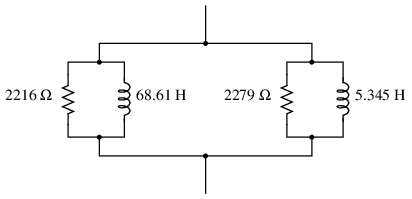
Challenge question: from the simple-parallel equivalent circuit shown here, can you generate an equivalent circuit that is simple-series? In other words, can you calculate the proper values of R and L , that when connected in series, will have the same total impedance as this circuit?
Fundamentally, this question asks students to generate an equivalent parallel R-X circuit from a given series R-X circuit. In this particular circuit, there are two series-connected R-X branches, resulting in an equivalent parallel circuit with four branches.
Calculating the circuit’s total impedance as a scalar figure involves simplifying the circuit once more into two components: a resistance and a reactance.
Question 54. (Click on arrow for answer)
It is not uncommon to see impedances represented in AC circuits as boxes, rather than as combinations of R, L, and/or C. This is simply a convenient way to represent what may be complex sub-networks of components in a larger AC circuit:

We know that any given impedance may be represented by a simple, two-component circuit: either a resistor and a reactive component connected in series, or a resistor and a reactive component connected in parallel. Assuming a circuit frequency of 250 Hz, determine what combination of series-connected components will be equivalent to this “box” impedance, and also what combination of parallel-connected components will be equivalent to this “box” impedance.
File Num: 00859

Once students learn to convert between complex impedances, equivalent series R-X circuits, and equivalent parallel R-X circuits, it becomes possible for them to analyze the most complex series-parallel impedance combinations imaginable without having to do arithmetic with complex numbers (magnitudes and angles at every step). It does, however, require that students have a good working knowledge of resistance, conductance, reactance, susceptance, impedance, and admittance, and how these quantities relate mathematically to one another in scalar form.
Question 55. (Click on arrow for answer)

We know that any given impedance may be represented by a simple, two-component circuit: either a resistor and a reactive component connected in series, or a resistor and a reactive component connected in parallel. Assuming a circuit frequency of 2 kHz, determine what combination of series-connected components will be equivalent to this “box” impedance, and also what combination of parallel-connected components will be equivalent to this “box” impedance.
File Num: 03296

All files with file num less than 4100 are Copyright 2003, Tony R. Kuphaldt, released under the Creative Commons Attribution License (v 1.0). All other files are Copyright 2022, David Williams, released under the Creative Commons Attribution License (V 4.0) This means you may do almost anything with this work, so long as you give proper credit.
To view a copy of the license, visit https://creativecommons.org/licenses/by/1.0/ , or https://creativecommons.org/licenses/by/4.0/ , or send a letter to Creative Commons, 559 Nathan Abbott Way, Stanford, California 94305, USA. The terms and conditions of this license allow for free copying, distribution, and/or modification of all licensed works by the general public.
23.11 Reactance, Inductive and Capacitive
Learning objectives.
By the end of this section, you will be able to:
- Sketch voltage and current versus time in simple inductive, capacitive, and resistive circuits.
- Calculate inductive and capacitive reactance.
- Calculate current and/or voltage in simple inductive, capacitive, and resistive circuits.
Many circuits also contain capacitors and inductors, in addition to resistors and an AC voltage source. We have seen how capacitors and inductors respond to DC voltage when it is switched on and off. We will now explore how inductors and capacitors react to sinusoidal AC voltage.
Inductors and Inductive Reactance
Suppose an inductor is connected directly to an AC voltage source, as shown in Figure 23.43 . It is reasonable to assume negligible resistance, since in practice we can make the resistance of an inductor so small that it has a negligible effect on the circuit. Also shown is a graph of voltage and current as functions of time.
The graph in Figure 23.43 (b) starts with voltage at a maximum. Note that the current starts at zero and rises to its peak after the voltage that drives it, just as was the case when DC voltage was switched on in the preceding section. When the voltage becomes negative at point a, the current begins to decrease; it becomes zero at point b, where voltage is its most negative. The current then becomes negative, again following the voltage. The voltage becomes positive at point c and begins to make the current less negative. At point d, the current goes through zero just as the voltage reaches its positive peak to start another cycle. This behavior is summarized as follows:
AC Voltage in an Inductor
When a sinusoidal voltage is applied to an inductor, the voltage leads the current by one-fourth of a cycle, or by a 90º 90º phase angle.
Current lags behind voltage, since inductors oppose change in current. Changing current induces a back emf V = − L ( Δ I / Δ t ) V = − L ( Δ I / Δ t ) . This is considered to be an effective resistance of the inductor to AC. The rms current I I through an inductor L L is given by a version of Ohm’s law:
where V V is the rms voltage across the inductor and X L X L is defined to be
with f f the frequency of the AC voltage source in hertz (An analysis of the circuit using Kirchhoff’s loop rule and calculus actually produces this expression). X L X L is called the inductive reactance , because the inductor reacts to impede the current. X L X L has units of ohms ( 1 H = 1 Ω ⋅ s 1 H = 1 Ω ⋅ s , so that frequency times inductance has units of ( cycles/s ) ( Ω ⋅ s ) = Ω ( cycles/s ) ( Ω ⋅ s ) = Ω ), consistent with its role as an effective resistance. It makes sense that X L X L is proportional to L L , since the greater the induction the greater its resistance to change. It is also reasonable that X L X L is proportional to frequency f f , since greater frequency means greater change in current. That is, Δ I /Δ t Δ I /Δ t is large for large frequencies (large f f , small Δ t Δ t ). The greater the change, the greater the opposition of an inductor.
Example 23.10
Calculating inductive reactance and then current.
(a) Calculate the inductive reactance of a 3.00 mH inductor when 60.0 Hz and 10.0 kHz AC voltages are applied. (b) What is the rms current at each frequency if the applied rms voltage is 120 V?
The inductive reactance is found directly from the expression X L = 2π fL X L = 2π fL . Once X L X L has been found at each frequency, Ohm’s law as stated in the Equation I = V / X L I = V / X L can be used to find the current at each frequency.

Solution for (a)
Entering the frequency and inductance into Equation X L = 2π fL X L = 2π fL gives
Similarly, at 10 kHz,
Solution for (b)
The rms current is now found using the version of Ohm’s law in Equation I = V / X L I = V / X L , given the applied rms voltage is 120 V. For the first frequency, this yields
The inductor reacts very differently at the two different frequencies. At the higher frequency, its reactance is large and the current is small, consistent with how an inductor impedes rapid change. Thus high frequencies are impeded the most. Inductors can be used to filter out high frequencies; for example, a large inductor can be put in series with a sound reproduction system or in series with your home computer to reduce high-frequency sound output from your speakers or high-frequency power spikes into your computer.
Note that although the resistance in the circuit considered is negligible, the AC current is not extremely large because inductive reactance impedes its flow. With AC, there is no time for the current to become extremely large.
Capacitors and Capacitive Reactance
Consider the capacitor connected directly to an AC voltage source as shown in Figure 23.44 . The resistance of a circuit like this can be made so small that it has a negligible effect compared with the capacitor, and so we can assume negligible resistance. Voltage across the capacitor and current are graphed as functions of time in the figure.
The graph in Figure 23.44 starts with voltage across the capacitor at a maximum. The current is zero at this point, because the capacitor is fully charged and halts the flow. Then voltage drops and the current becomes negative as the capacitor discharges. At point a, the capacitor has fully discharged ( Q = 0 Q = 0 on it) and the voltage across it is zero. The current remains negative between points a and b, causing the voltage on the capacitor to reverse. This is complete at point b, where the current is zero and the voltage has its most negative value. The current becomes positive after point b, neutralizing the charge on the capacitor and bringing the voltage to zero at point c, which allows the current to reach its maximum. Between points c and d, the current drops to zero as the voltage rises to its peak, and the process starts to repeat. Throughout the cycle, the voltage follows what the current is doing by one-fourth of a cycle:
AC Voltage in a Capacitor
When a sinusoidal voltage is applied to a capacitor, the voltage follows the current by one-fourth of a cycle, or by a 90º 90º phase angle.
The capacitor is affecting the current, having the ability to stop it altogether when fully charged. Since an AC voltage is applied, there is an rms current, but it is limited by the capacitor. This is considered to be an effective resistance of the capacitor to AC, and so the rms current I I in the circuit containing only a capacitor C C is given by another version of Ohm’s law to be
where V V is the rms voltage and X C X C is defined (As with X L X L , this expression for X C X C results from an analysis of the circuit using Kirchhoff’s rules and calculus) to be
where X C X C is called the capacitive reactance , because the capacitor reacts to impede the current. X C X C has units of ohms (verification left as an exercise for the reader). X C X C is inversely proportional to the capacitance C C ; the larger the capacitor, the greater the charge it can store and the greater the current that can flow. It is also inversely proportional to the frequency f f ; the greater the frequency, the less time there is to fully charge the capacitor, and so it impedes current less.
Example 23.11
Calculating capacitive reactance and then current.
(a) Calculate the capacitive reactance of a 5.00 µF capacitor when 60.0 Hz and 10.0 kHz AC voltages are applied. (b) What is the rms current if the applied rms voltage is 120 V?
The capacitive reactance is found directly from the expression in X C = 1 2π fC X C = 1 2π fC . Once X C X C has been found at each frequency, Ohm’s law stated as I = V / X C I = V / X C can be used to find the current at each frequency.
Entering the frequency and capacitance into X C = 1 2π fC X C = 1 2π fC gives
The rms current is now found using the version of Ohm’s law in I = V / X C I = V / X C , given the applied rms voltage is 120 V. For the first frequency, this yields
The capacitor reacts very differently at the two different frequencies, and in exactly the opposite way an inductor reacts. At the higher frequency, its reactance is small and the current is large. Capacitors favor change, whereas inductors oppose change. Capacitors impede low frequencies the most, since low frequency allows them time to become charged and stop the current. Capacitors can be used to filter out low frequencies. For example, a capacitor in series with a sound reproduction system rids it of the 60 Hz hum.
Although a capacitor is basically an open circuit, there is an rms current in a circuit with an AC voltage applied to a capacitor. This is because the voltage is continually reversing, charging and discharging the capacitor. If the frequency goes to zero (DC), X C X C tends to infinity, and the current is zero once the capacitor is charged. At very high frequencies, the capacitor’s reactance tends to zero—it has a negligible reactance and does not impede the current (it acts like a simple wire). Capacitors have the opposite effect on AC circuits that inductors have .
Resistors in an AC Circuit
Just as a reminder, consider Figure 23.45 , which shows an AC voltage applied to a resistor and a graph of voltage and current versus time. The voltage and current are exactly in phase in a resistor. There is no frequency dependence to the behavior of plain resistance in a circuit:
AC Voltage in a Resistor
When a sinusoidal voltage is applied to a resistor, the voltage is exactly in phase with the current—they have a 0º 0º phase angle.
As an Amazon Associate we earn from qualifying purchases.
This book may not be used in the training of large language models or otherwise be ingested into large language models or generative AI offerings without OpenStax's permission.
Want to cite, share, or modify this book? This book uses the Creative Commons Attribution License and you must attribute OpenStax.
Access for free at https://openstax.org/books/college-physics-2e/pages/1-introduction-to-science-and-the-realm-of-physics-physical-quantities-and-units
- Authors: Paul Peter Urone, Roger Hinrichs
- Publisher/website: OpenStax
- Book title: College Physics 2e
- Publication date: Jul 13, 2022
- Location: Houston, Texas
- Book URL: https://openstax.org/books/college-physics-2e/pages/1-introduction-to-science-and-the-realm-of-physics-physical-quantities-and-units
- Section URL: https://openstax.org/books/college-physics-2e/pages/23-11-reactance-inductive-and-capacitive
© Jan 19, 2024 OpenStax. Textbook content produced by OpenStax is licensed under a Creative Commons Attribution License . The OpenStax name, OpenStax logo, OpenStax book covers, OpenStax CNX name, and OpenStax CNX logo are not subject to the Creative Commons license and may not be reproduced without the prior and express written consent of Rice University.

AC Electric Machines pp 55–86 Cite as
Solutions of Problems: Induction Machines
- Mehdi Rahmani-Andebili 2
- First Online: 02 November 2022
266 Accesses
In this chapter, the problems of the third chapter are fully solved, in detail, step-by-step, and with different methods.
- Induction motor
- Induction generator
- Induction machine
- Star-connected stator
- Delta-connected stator
- Electromotive force (emf)
- Starting torque
- Rated torque
- Revolving field of rotor
- Revolving field of stator
- Input power
- Air gap power
- Mechanical power
- Output power
- Core power loss
- Stator cupper power loss
- Rotor copper power loss
- Electromagnetic power
- Electromagnetic torque
- Output torque
- Rotational power loss
- External resistance
- Wound rotor induction motor
- Squirrel-cage induction motor
- Wound rotor induction generator
- Squirrel-cage induction generator
- Full-load torque
- Maximum torque
- Parameters of equivalent circuit
- Ohmic power loss
- Stationary impedance of rotor
- Stable operating region
- Unstable operating region
- Rotor resistance
- Rotor impedance
- Stator impedance
- Air gap magnetic flux
- Phase current
- Line current
- Synchronous speed
- Power flow diagram
- Single-phase
- Three-phase
- Full-load condition
- Half-load condition
- No-load condition
- Per unit (p.u.)
- Lagging power factor
- Leading power factor
- Active power
- Reactive power
- Complex power
This is a preview of subscription content, log in via an institution .
Buying options
- Available as PDF
- Read on any device
- Instant download
- Own it forever
- Available as EPUB and PDF
- Compact, lightweight edition
- Dispatched in 3 to 5 business days
- Free shipping worldwide - see info
- Durable hardcover edition
Tax calculation will be finalised at checkout
Purchases are for personal use only
Author information
Authors and affiliations.
Department of Engineering and Physics, University of Central Oklahoma, Edmond, OK, USA
Mehdi Rahmani-Andebili
You can also search for this author in PubMed Google Scholar
Rights and permissions
Reprints and permissions
Copyright information
© 2023 The Author(s), under exclusive license to Springer Nature Switzerland AG
About this chapter
Cite this chapter.
Rahmani-Andebili, M. (2023). Solutions of Problems: Induction Machines. In: AC Electric Machines. Springer, Cham. https://doi.org/10.1007/978-3-031-15139-2_4
Download citation
DOI : https://doi.org/10.1007/978-3-031-15139-2_4
Published : 02 November 2022
Publisher Name : Springer, Cham
Print ISBN : 978-3-031-15138-5
Online ISBN : 978-3-031-15139-2
eBook Packages : Energy Energy (R0)
Solver Title
Generating PDF...
- Pre Algebra Order of Operations Factors & Primes Fractions Long Arithmetic Decimals Exponents & Radicals Ratios & Proportions Percent Modulo Number Line Mean, Median & Mode
- Algebra Equations Inequalities System of Equations System of Inequalities Basic Operations Algebraic Properties Partial Fractions Polynomials Rational Expressions Sequences Power Sums Interval Notation Pi (Product) Notation Induction Logical Sets Word Problems
- Pre Calculus Equations Inequalities Scientific Calculator Scientific Notation Arithmetics Complex Numbers Polar/Cartesian Simultaneous Equations System of Inequalities Polynomials Rationales Functions Arithmetic & Comp. Coordinate Geometry Plane Geometry Solid Geometry Conic Sections Trigonometry
- Calculus Derivatives Derivative Applications Limits Integrals Integral Applications Integral Approximation Series ODE Multivariable Calculus Laplace Transform Taylor/Maclaurin Series Fourier Series Fourier Transform
- Functions Line Equations Functions Arithmetic & Comp. Conic Sections Transformation
- Linear Algebra Matrices Vectors
- Trigonometry Identities Proving Identities Trig Equations Trig Inequalities Evaluate Functions Simplify
- Statistics Mean Geometric Mean Quadratic Mean Average Median Mode Order Minimum Maximum Probability Mid-Range Range Standard Deviation Variance Lower Quartile Upper Quartile Interquartile Range Midhinge Standard Normal Distribution
- Physics Mechanics
- Chemistry Chemical Reactions Chemical Properties
- Finance Simple Interest Compound Interest Present Value Future Value
- Economics Point of Diminishing Return
- Conversions Roman Numerals Radical to Exponent Exponent to Radical To Fraction To Decimal To Mixed Number To Improper Fraction Radians to Degrees Degrees to Radians Hexadecimal Scientific Notation Distance Weight Time Volume
- Pre Algebra
- One-Step Addition
- One-Step Subtraction
- One-Step Multiplication
- One-Step Division
- One-Step Decimals
- Two-Step Integers
- Two-Step Add/Subtract
- Two-Step Multiply/Divide
- Two-Step Fractions
- Two-Step Decimals
- Multi-Step Integers
- Multi-Step with Parentheses
- Multi-Step Rational
- Multi-Step Fractions
- Multi-Step Decimals
- Solve by Factoring
- Completing the Square
- Quadratic Formula
- Biquadratic
- Logarithmic
- Exponential
- Rational Roots
- Floor/Ceiling
- Equation Given Roots
- Newton Raphson
- Substitution
- Elimination
- Cramer's Rule
- Gaussian Elimination
- System of Inequalities
- Perfect Squares
- Difference of Squares
- Difference of Cubes
- Sum of Cubes
- Polynomials
- Distributive Property
- FOIL method
- Perfect Cubes
- Binomial Expansion
- Negative Rule
- Product Rule
- Quotient Rule
- Expand Power Rule
- Fraction Exponent
- Exponent Rules
- Exponential Form
- Logarithmic Form
- Absolute Value
- Rational Number
- Powers of i
- Partial Fractions
- Is Polynomial
- Leading Coefficient
- Leading Term
- Standard Form
- Complete the Square
- Synthetic Division
- Linear Factors
- Rationalize Denominator
- Rationalize Numerator
- Identify Type
- Convergence
- Interval Notation
- Pi (Product) Notation
- Boolean Algebra
- Truth Table
- Mutual Exclusive
- Cardinality
- Caretesian Product
- Age Problems
- Distance Problems
- Cost Problems
- Investment Problems
- Number Problems
- Percent Problems
- Addition/Subtraction
- Multiplication/Division
- Dice Problems
- Coin Problems
- Card Problems
- Pre Calculus
- Linear Algebra
- Trigonometry
- Conversions

Most Used Actions
Number line.
- prove\:by\:induction\:\sum_{k=1}^{n}k^{2}=\frac{n(n+1)(2n+1)}{6}
- prove\:by\:induction\:\sum_{k=1}^{n}k^{3}=\frac{n^{2}(n+1)^{2}}{4}
- prove\:by\:induction\:\sum_{k=1}^{n}k(k+1)=\frac{n(n+1)(n+2)}{3}
- How do you prove series value by induction step by step?
- To prove the value of a series using induction follow the steps: Base case: Show that the formula for the series is true for the first term. Inductive hypothesis: Assume that the formula for the series is true for some arbitrary term, n. Inductive step: Using the inductive hypothesis, prove that the formula for the series is true for the next term, n+1. Conclusion: Since the base case and the inductive step are both true, it follows that the formula for the series is true for all terms.
- What is the principle of induction?
- The principle of induction is a basic principle of logic and mathematics that states that if a statement is true for the first term in a series, and if the statement is true for any term n assuming that it is true for the previous term n-1, then the statement is true for all terms in the series.
- What is induction in calculus?
- In calculus, induction is a method of proving that a statement is true for all values of a variable within a certain range. This is done by showing that the statement is true for the first term in the range, and then using the principle of mathematical induction to show that it is also true for all subsequent terms.
- How do you prove divisibility by induction?
- To prove divisibility by induction show that the statement is true for the first number in the series (base case). Then use the inductive hypothesis and assume that the statement is true for some arbitrary number, n. Using the inductive hypothesis, prove that the statement is true for the next number in the series, n+1. Since the base case is true and the inductive step shows that the statement is true for all subsequent numbers, the statement is true for all numbers in the series.
induction-calculator
- Middle School Math Solutions – Equation Calculator Welcome to our new "Getting Started" math solutions series. Over the next few weeks, we'll be showing how Symbolab...
Please add a message.
Message received. Thanks for the feedback.
Forgot password? New user? Sign up
Existing user? Log in
Already have an account? Log in here.
- Gerald Huang
- Hua Zhi Vee
- Aditya Raut
- Samuraiwarm Tsunayoshi
- Kuldeep Guha Mazumder
- shivamani patil
- Arya Samanta
- Rohit Udaiwal
The principle of mathematical induction (often referred to as induction , sometimes referred to as PMI in books) is a fundamental proof technique. It is especially useful when proving that a statement is true for all positive integers \(n.\)
Induction is often compared to toppling over a row of dominoes. If you can show that the dominoes are placed in such a way that tipping one of them over ensures that the next one will fall and then you tip the first one over, you can assure that all the dominoes will eventually fall.
Formulation
Examples - summation, examples - inequalities, examples - divisibility, examples - recurrence relations, examples - functional equations, examples - differentiation, examples - integration, examples - combinatorics applications, problem solving, proof of mathematical induction.
Let's say you have a statement \(P(n)\) that depends on a positive integer \(n\) and you have to prove that this statement holds for all positive integers \(n\). How would you do that?
Step 1 : At first you prove that \(P(k)\) is true where \(k\) is the starting value of your statement \(\big(\)for example, if your statement is \( \small\frac {n(n + 1)}{2}\) for all integers greater than 98, you must prove 99 is a valid solution\(\big)\). In other words, you must prove the starting value of your statement is valid. Step 2 : Then you show that if the statement is true for any arbitrary positive integer \(x\), then it is true for \(x+1\).
If you can do both of these things, you've proved that the statement is true for all positive integers \(n\). Congratulations!
\(\) Take some time to think about why this argument works. Remember that you proved that \(P(k)\) is true, where \(k\) is your starting value. You also proved that \(P(k+1)\) is also true \((\)if \(x\) is equal to \(k,\) which is a valid assumption\().\) Therefore, \(P\big((k+1)+1\big)\) or \(P(k+2)\) would also be true. By the same reasoning, \(P(k+3)\) is also true and so on. Therefore, proving the two steps mentioned above is enough to prove that the statement holds for all positive integers above your starting value \(k\).
For further details, see Proof of Mathematical Induction .
Main article: Writing a Proof by Induction
Now that we've gotten a little bit familiar with the idea of proof by induction, let's rewrite everything we learned a little more formally.
Proof by Induction Step 1: Prove the base case This is the part where you prove that \(P(k)\) is true if \(k\) is the starting value of your statement. The base case is usually showing that our statement is true when \(n=k\). Step 2: The inductive step This is where you assume that \(P(x)\) is true for some positive integer \(x\). This assumption is called the inductive hypothesis . Then you show that if \(P(x)\) were true, so is \(P(x+1)\). This is the inductive step . In short, the inductive step usually means showing that \(P(x)\implies P(x+1)\). Notice the word "usually," which means that this is not always the case. You'll learn that there are many variations of induction where the inductive step is different from this, for example, the strong induction
That's basically all there's to it. At the start, it is best to follow a standardized format so that you know exactly what to write. Once you get comfortable with it, you can simplify the proof further.
Sometimes, flawed induction proofs happen.
As always, the best way to learn is through examples. So let's begin!
Summations are often the first example used for induction. It is often easy to trace what the additional term is, and how adding it to the final sum would affect the value.
Prove that \(1+2+3+\cdots +n=\frac{n(n+1)}{2}\) for all positive integers \(n\). We want to prove something for "all positive integers \(n,\)" and induction seems like a good way to start. First, we verify the base case. Although it seems obvious here (the base case is 1 because it is the first positive integer), this is a crucial step. Sometimes not verifying the base case can lead to fallacious proofs. Our statement is true for \(n=1\) (our base case) because with \(n=1\) the left-hand side is \(1\) and the right-hand side is \(\frac{1(1+1)}{2},\) which is also \(1\). Now let us assume that the statement is true for some positive integer \(k\). This is our induction hypothesis. If we can show that the statement is true for \(k+1\), our proof is done. By our induction hypothesis, we have \[1+2+3+\cdots+ k=\frac{k(k+1)}{2}.\] Now if we add \(k+1\) to both sides, we get \[\begin{array} { l l } 1+2+3+\cdots +k+(k+1) & =\frac{k(k+1)}{2}+(k+1) \\ & = (k+1)\left( \frac{k}{2} + 1 \right) \\ & = \frac{ (k+1)(k+2)} { 2} \\ & = \frac{ (k+1)\big((k+1)+1\big)} { 2},\\ \end{array} \] which means that if our statement is true for \(k\), it is true for \(k+1\) as well. This proves the statement true for all positive integers \(n\). We're done!\(\ _\square\)
Prove that \(\displaystyle{\sum_{k=1}^{n}(2k-1)}=n^2\) for all positive integers. Since \(2\times1-1=1^2\), the statement holds when \(n=1\). Now let's assume that \(1+3+5+\cdots+(2k-1)=k^2\) for some positive integer \(k\). Then add \(2k+1\) to both sides of the equation, which gives \[1+3+5+\cdots+(2k-1)+(2k+1)=k^2+(2k+1)=(k+1)^2.\] Thus if the statement holds when \(n=k\), it also holds for \(n=k+1\). Therefore the statement is true for all positive integers \(n\).\(\ _\square\)
Prove that \(\displaystyle{\sum_{k=1}^{n}2^k}=2^{n+1}-2\) for all positive integers. Since \(2^1=2^2-2=2\), the statement holds when \(n=1\). Now let's assume that \(2^1+2^2+\cdots+2^k=2^{k+1}-2\) for some positive integer \(k\). Then add \(2^{k+1}\) to both sides of the equation, which gives \[2^1+2^2+\cdots+2^k+2^{k+1}=2^{k+1}+2^{k+1}-2=2^{k+2}-2.\] Thus if the statement holds when \(n=k\), it also holds for \(n=k+1\). Therefore the statement is true for all positive integers \(n\).\(\ _\square\)
\[1(1!)+2(2!)+3(3!)+4(4!)+\cdots +2014(2014)! = n!-1\]
What is the value of \(n?\)
Induction can also be used for proving inequalities. Just apply the same method we have been using. Once again, it is easy to trace what the additional term is, and how it affects the final sum.
Prove that \(2^n>n\) for all positive integers \(n.\) Since \(2^1>1\), the statement holds when \(n=1\). Now let's assume that \(2^k>k\) for some positive integer \(k\) which is larger than \(1\). Then multiply both sides of the equation by \(2\), which gives \[2^k\times2=2^{k+1}>2k.\] Since we assumed that \(k>1\), \(2k>k+1\) is always true. Hence we have \[2^{k+1}>2k>k+1.\] Thus if the given statement holds when \(n=k\), it also holds for \(n=k+1\). Therefore the statement is true for all positive integers \(n\).\(\ _\square\)
Prove that when \(h>0\), the inequality \((1+h)^n>1+nh\) holds for all positive integers \(n\geq2\). Since \((1+h)^2=h^2+2h+1>1+2h\), the statement holds when \(n=2\). Now let's assume that \((1+h)^k>1+kh\) for some positive integer \(k\) that is larger than \(2\). Then multiply both sides of the equation by \(1+h\), which gives \[ \begin{array} { l l } (1+h)^k\times(1+h)=(1+h)^{k+1} & >(1+kh)(1+h) \\ & =kh^2+(k+1)h+1 \\ & >1+(k+1)h. \end{array} \] Thus if the statement holds when \(n=k\), it also holds for \(n=k+1\). Therefore the statement is true for all positive integers \(n\geq2\).\(\ _\square\)
Prove, by mathematical induction, \( n^2 > 2n + 1\) for \(n \geq 4. \) We attempt to verify that this statement holds true for the base case, that is, \(4^{2} > 2(4) + 1 \), which is true by nature. Now, we suppose that for some arbitrary integer, the statement will hold true: \(k^{2} > 2k + 1, k> 4. \) If this is true (by assumption), then if the next value of \(k,\) which is \((k+1),\) holds true, then by the principles of mathematical induction the whole statement is true within the domain of \( n: \) \[\begin{align*}LHS &= (k+1)^{2} \\ &= k^2 + 2k + 1 \\ &> (2k + 1) + 2k + 1&&\qquad \text{ (by our assumption)}\\ &= 4k + 2 \\ &= 2k + 2k + 2 \\ &\geq 2k + 10&&\qquad \text{ (since we defined } k \geq 4\text{)} \\ &> 2k + 3 \\ &= 2k + 2 + 1 \\ &= 2(k+1) + 1 \\ &= RHS,\end{align*}\] which implies \(LHS > RHS. \) Thus, if the statement holds when \(n=k \), it also holds for \(n=k+1\). Therefore, the statement holds true within the condition \(n\geq 4\).\(\ _\square\)
Sometimes the application of induction to inequalities cannot happen directly. This happens when the side that is supposed to be smaller is increased to a larger extent. For more details, see "Stronger" Induction .
For proving divisibility, induction gives us a way to slowly build up what we know. This allows us to show that certain terms are divisible, even without knowing number theory or modular arithmetic .
Prove that \(2^{2n}-1\) is always divisible by \(3\) if \(n\) is a positive integer. Again we have to prove something about "all positive integers \(n.\)" For \(n=1,\) our statement is true since \(2^{2\times 1}-1\) is equal to \(3\) and thus divisible by \(3\). Now we have to show that if the statement is true for some positive integer \(k\), it is true for \(k+1\). If the statement is true for \(k\), we can set \(2^{2k}-1=3x\) for some positive integer \(x\). Note that \[2^{2(k+1)}-1=2^{2k+2}-1=2^2\cdot 2^{2k}-1=4\cdot 2^{2k}-1=3\cdot 2^{2k}+2^{2k}-1.\] Since \(2^{2k}-1=3x\), this can be rewritten as \(3\big(2^{2k}+x\big),\) which is obviously divisible by \(3\). We've been able to show the inductive step and that completes our proof. \(_\square\)
Show that, for all positive integers \(n\), \[ 64 \, \Big| \, 3^{2n+1} + 40 n - 67. \] Let \(P_n \) be the proposition \( 64~|~3^{2n+1}+40n-67\) for all positive integers \(n\). First, consider the base case where \(n = 1\). Observe that \[ 3^{2\cdot 1 + 1} + 40 (1) - 67 = 27 + 40 - 67 = 0 \] and that \(64\) divides \(0\) since \( 64 \times 0 = 0.\) Then \(P_1\) is true. Now, assume \(P_{k}\) is true for some \(k \in \text{domain},\) then \( 64 ~|~3^{2k+1} + 40k - 67\). This gives \[ \begin{array} { l l } 64~|~ 3^{2k+3}+40k\times 9 - 67\times 9\\ 64~|~ 3^{2k+3}+40k + 40 + (40 \times 8k - 40) -67 + (-67\times 8)\\ 64~|~ 3^{2k+3}+40(k+1) -67 + (320k -576)\\ 64~|~ 3^{2(k+1)+1}+40(k+1) -67. \end{array} \] Hence \(P_{k}\) true \( \implies P_{k+1} \) true. By mathematical induction, since the base case where \(n=1\) is true and \(P_{k}\) is true, \(P_{k+1}\) true. Therefore, \(P_{n}\) is true for all positive integers \(n\). \(_\square\)
In the above question, it was difficult to utilize the induction hypothesis. Most people found it difficult to deal with the \(3^{2k+3}\) term, and the solution follows by understanding that \(3^{2k+3}=9\times 3^{2k+1} \).
We can actually show the base case for \(n=0\), which is a simpler calculation to do. While it is not immediately obvious why we would want to do this, imagine if the question asked to show this for positive integers \( n \geq 100\). Would you want to evaluate \(3^{201}?\) Not likely.
When you are given the closed form solution of a recurrence relation, it can be easy to use induction as a way of verifying that the formula is true.
Consider the sequence of numbers given by \( a_1 = 1, a_{n+1} = 2 \times a_n + 1 \) for all positive integers \(n\). Show that \( a_n = 2 ^ n - 1 \). Base case: Let's check \( n = 1 \). LHS: \( a_1 = 1.\ \) RHS: \( 2^ 1 - 1 = 2 - 1 = 1 \). Hence, the base case is true. Induction step: Assume that \( a_k = 2^k - 1 \) for some \(k\). Then we have \( a_{k+1 } = 2 \times a_k + 1 = 2 \times ( 2 ^ k - 1) + 1 = 2 \times 2^ { k } -2 + 1 = 2^{k+1} - 1 . \) Hence, the inductive step is true, and the result follows. \(_\square\)
Consider the Fibonacci sequence where \( F_0 = 0 , F_1 = 1 , F_n = F_{n-1} + F_{n-2} \) for all positive integers \(n\). Prove that \[ F_0 + F_1 + F_2 + \cdots + F_n = F_{n+2} -1 \] for all \( n \geq 0. \) Base case: Let \(n=0\). The LHS is \( F_0 = 0 \) and the RHS is \( F_2 - 1 = 0 \). Induction step: Assume that the statement is true for \(n,\) i.e. \[ F_0 + F_1 + F_2 + \cdots + F_n = F_{n+2} -1. \] Then \[ \begin{eqnarray} F_0 + F_1 + F_2 + \cdots + F_n + F_{n+1} &=& ( F_0 + F_1 + F_2 + \cdots + F_n) + F_{n+1} \\ &=& ( F_{n+2} -1 ) + F_{n+1} &\qquad \text{(by assumption)}\\ &=& ( F_{n+2} + F_{n+1} ) -1 \\ &=& F_{n+3} -1, \end{eqnarray} \] which is the statement for \( n+1 \). This completes the induction. \(_\square \)
Consider the sequence of numbers given by \( b_1 = 3, b_2 = 9 \) and \( b_{n+2} = b_{n+1} + 2 \times b_n \) for all positive integers \(n\). Show that \( b_n = 2 ^ { n+1} + (-1) ^ n \). Base case: Let's check \( n = 1, 2 \). LHS: \( b_1 = 3 \). RHS: \( 2 ^ 2 + (-1)^1 = 4 - 1 = 3 \). LHS: \( b_ 2 = 9 \). RHS: \( 2^3 + (-1)^2 = 8 + 1 = 9 \). Hence the base case is true. Induction step: Assume that \( b_n = 2 ^{n+1} + (-1)^n \) and \( b_{n+1} = 2^{n+2} + (-1)^{n+1} \). Then we have \[\begin{array} {l l } b_{n+2} & = b_{n+1} + 2 \times b_n \\ & = \left(2^{n+2} + (-1)^{n+1} \right) + 2 \times \left(2 ^{n+1} + (-1)^n\right) \\ &= \left(2^{n+2} + 2^{n+2}\right) + \left( (-1)^{n+1} - 2 \times (-1)^{n+1} \right) \\ &= 2 \times 2 ^ {n+2} + (-1) \times (-1) ^ { n + 1 } \\ &= 2^{n+3} + (-1)^{n+2} \\ \end{array} \] Hence the inductive step is true and the result follows. \(_\square\) Note: Why did we do 2 bases cases? This is because in the inductive step we have to use 2 equations.
As you can see, induction is a powerful tool for us to verify an identity. However, if we were not given the closed form, it could be harder to prove the statement by induction. Instead, we will need to study linear recurrence relations in order to understand how to solve them.
Let \(b_{k,n}\) be the \(k^\text{th}\) element of the \(n^\text{th}\) row of Pascal's triangle, with row \(1\) being \(\{1\},\) row \(2\) being \(\{1,1\},\) etc. Also, the \(1^\text{st}\) element of each row is \(1.\)
Find the value of
\[(b_{3,2015})^2 - \sum_{i=1}^{2013} i^3.\]
Details and Assumptions:
- For example, \(b_{1,1} = 1, b_{2,3} = 2,\) and \(b_{5,6} = 5.\)
Image Credit: Wikipedia Pascal Triangle
The following theorem is an extremely important fact in functional equations.
\(f\) is a real-valued function defined on the rationals such that \(f(a+b)=f(a)+f(b)\) for all rational values \(a\) and \(b\). Then \(f(x)=xf(1)\) for all rational values \(x\).
We provide a sketch of the proof. Details are left to the reader. We first show by induction that \( f(na) = nf(a) \) for all positive integers \(n\). We then show that \(f(0)=0, f(-na)=-nf(a)\), so the statement holds for all integers. By substituting \(a=1\) and \(n=n,\) we get that \(f(n) = nf(a) \) for all integers. We substitute \( a = \frac {m}{n}\) and \(n=n\) to get that \[ m f(1) = f(m) = n f\left(\frac {m}{n}\right) \implies f\left(\frac {m}{n}\right) = \frac {m}{n} f(1) \] for all integers \(n\) and \(m\). \(_\square\)
Let \(f\) be a function from \(\mathbb{Z}^+\) to \(\mathbb{Z}^*\) such that
- \(f(2n)=2f(n)+1\)
- \(f(2n+1)=2f(n).\)
Find the smallest value of \(n\) such that \(f(n)=1994\).
Notation: \(\mathbb Z^+ \) denotes the set of positive integers, and \(\mathbb{Z}^*\) denotes the set of non-negative integers.
How many functions \(f(x)\) from integers to integers are there such that for all integer \(n\) we have
\[f\big(f(n)+1\big)=n?\]
Note: The main point is not really solving it, but to prove your result.
\[ \Large f(x;n) = \underbrace{ x^{x^{.^{.^x}}} }_{\text{number of } x \text{'s } =\ n } \]
\(\) A positive integer \(n\) is randomly chosen between 1 and 10000 inclusive for the function described above.
If \(p\) denotes the probability that \( \displaystyle \lim_{x \to 0} f(x;n) = 1, \) what is the value of \( \left \lfloor 1000p \right \rfloor?\)
\[ { I }(n)=\int _{ 0 }^{ \frac { \pi }{ 4 } }{ \cos ^{ n }{ x } \, dx },\]
if \(I(5) = \frac { a\sqrt { b } }{ c } \), what is \(a + b + c?\)
- You can use \(\int { \cos { ax } } \, dx =\frac { 1 }{ a } \sin { ax } \).
- \(a, b, c\) are positive integers, \( \gcd(a,c)=1,\) and \(b\) is a square-free integer.
Which of the following is/are used in the derivation of
\[(s-1)! \equiv \int_{0}^{\infty} e^{-t}t^{s-1} \, dt\, ?\]
A. \(\ \) Integration by parts B. \(\ \) U-substitution C. \(\ \) Induction
A country has \(n\) cities. Any two cities are connected by a one-way road. Show that there is a route that passes through every city. The statement is obviously true for \(n=1\) or \(n=2\). So we're clear in the "base-case department." But how do we show the inductive step, that is, if we know that there is a route for a country with \(k\) cities, how do we show that a route exists for a country with \((k+1)\) cities? Let's write down what we already know. Let's say the \(k\) cities are \(C_1, C_2, C_3,\cdots, C_{k}\) and there is a route \[C_{1}\rightarrow C_{2} \rightarrow C_{3} \rightarrow \cdots\rightarrow C_k\] that passes through all of them. This is our induction hypothesis. Now we have to show the inductive step. In other words, if we have another city \(C_{k+1}\), we have to show that it is possible to insert it somewhere in the route above. We know that every two cities are connected by a one-way road. That means there is a road between \(C_k\) and \(C_{k+1}\). Can we add \(C_{k+1}\) to the end of the route like that? No, because the roads are one-way and thus it is very much possible that the road between \(C_k\) and \(C_{k+1}\) may go the wrong way. We can't simply say that our route is \[C_1 \rightarrow C_2 \rightarrow C_3 \rightarrow \cdots \rightarrow C_k \rightarrow C_{k+1}\] and that we are done with it. It's a bit more complicated than that. However, all hope is not gone. Remember that any two cities are connected by a road. There is a possibility that \(C_{k+1} \rightarrow C_1\). If that is the case, we're done because we have the route \[ C_{k+1} \rightarrow C_1 \rightarrow C_2\rightarrow C_3 \rightarrow \cdots \rightarrow C_k.\] If that is not the case, there exists an \(i\), with \(1\leq i\leq k,\) such that \(C_i \rightarrow C_{k+1}\). Take the largest such \(i\). By definition, we have \(C_i\rightarrow C_{k+1}\rightarrow C_{i+1}\). Now we can insert \(C_{k+1}\) in between these two cities and we have the route \[C_1\rightarrow C_2\rightarrow \cdots C_i\rightarrow C_{k+1}\rightarrow C_{i+1}\rightarrow \cdots \rightarrow C_k,\] which completes our proof. \(_\square\) Note : There's a possibility that \(C_{i+1}=C_{k+1}\). That just means that you have to take \(C_{k+1}\) to the end of the route.
For some positive integers \(n\), there exists a polynomial in \(n\) variables whose image is exactly the set of the real positive numbers (note that 0 is not included in this set). The values of \(n\) verifying that property are called Bremen numbers .
Find the sum of all the Bremen numbers smaller than or equal to 30.
Submit 0 as your answer if you believe that there does not exist any Bremen number smaller than or equal to 30.
Here are some tips:
- Know when induction is a good approach. Problems containing the phrase "prove for all positive integers \(n\)" are good candidates for induction.
- Never miss the base case. Although most of the times the base case is obvious, the proof isn't complete unless you show it. Not justifying the base case leads to a lot of fallacious proofs.
- If you want to use induction in a problem, make sure you have at least some sort of idea about how you're going to link \(P(k+1)\) to \(P(k).\)
- Sometimes proving something harder is easier! See "Stronger" Induction .
- Sometimes starting with a smaller base case makes calculation easier. Sometimes starting with a larger base case makes the induction step easier. Induction can also be used on finite discrete sets.
- You do not always induct on the variable \(n.\)
- If the hypothesis is given, questions usually test your mathematical ability to manipulate values. If the proposition is not given, it tests your ability to make sense of a series and spot any underlying pattern crucial to the solution.
- Though induction can establish the truthfulness of a statement, it rarely provides the motivation/reasoning behind the problem. However, it might provide a simpler solution.
Consider an 8 by 8 square grid with 1 random tile removed. Show that the remaining area can be completely tiled with 21 L-shaped triminos. This might seem like a strange problem for induction because there is no variable to induct on. The trick to this problem is to instead show that \[\text{a } 2^n \times 2^n \text{ square grid with }1\text{ random tile removed can be completely tiled with L-shaped triminos}.\] Give it a try!
Let \(S\) be a set of positive integers with the following properties: (1) The integer 1 belongs to the set. (2) Whenever integer \(k\) is in \(S\), the next integer \(k+1\) must also be in \(S\). Then \(S\) is the set of all positive integers.
This statement seems almost immediately obvious. A proof is provided for completeness but is not essential in understanding induction.
We will prove this theorem by contradiction. Let \(T\) be the set of all positive integers not in \(S\). By assumption, \(T\) is non-empty. Hence, according to the well-ordering principle, it must contain the smallest element, which we will denote by \(\alpha\). By (1), \(0 < \alpha-1 < \alpha\). Since \( \alpha\) is the smallest integer in \(T\), this implies that \( \alpha-1 \not\in T \implies (\alpha-1)\in S \). By (2), \(S\) must also contain \( (\alpha-1)+1=\alpha\). This contradicts the assumption that \(\alpha\in\) \(T\). Hence, set \(T\) is empty and set \(S\) contains all positive integers. \(_\square \)
- Flawed Induction Proofs
Problem Loading...
Note Loading...
Set Loading...
- School Guide
- Class 12 Syllabus
- Class 12 Revision Notes
- Maths Notes Class 12
- Physics Notes Class 12
- Chemistry Notes Class 12
- Biology Notes Class 12
- NCERT Solutions Class 12 Maths
- RD Sharma Solutions Class 12
- Reflection and Laws of Reflection
- Electromagnetic Spectrum
- Intrinsic Semiconductors and Extrinsic Semiconductors
- Photoelectric Effect - Definition, Equation, Characteristics, Applications
- Faraday's Law and Lenz's Law of Electromagnetic Induction
- Experiments of Faraday and Henry
- Superposition and Interference
- Hysteresis Loop - Definition, Energy Loss, Advantages, Sample Questions
- Carbon Resistors - Definition, Working, Uses, Advantages
- Potentiometer - Definition, Working Principle, Types
- Electric Field due to a Point Charge
- Diamagnetic Materials - Definition, Properties, Applications
- Basic Properties of Electric Charge
- Ferromagnetism - Definition, Causes, Properties, Hysteresis
- Superposition Principle and Continuous Charge Distribution
- Ohm's Law - Definition, Formula, Applications, Limitations
- Nuclear Reactions - Definition, Types, Examples
- Earth's Magnetic Field - Definition, Causes, Components
- Moving Coil Galvanometer
Problems on Self and Mutual Inductance
Electromagnetic induction , often known as induction, is a process in which a conductor is placed in a certain position and the magnetic field varies or remains stationary as the conductor moves. A voltage or EMF (Electromotive Force) is created across the electrical conductor as a result of this.
Michael Faraday discovered this electromagnetic induction rule. He built up a leading wire similar to the diagram below, which he linked to a device that measured the voltage across the circuit. The voltage in the circuit is measured when a bar magnet passes through the device. The significance of this is that it is a method of creating electrical energy in a circuit by employing magnetic fields rather than batteries. The principle of electromagnetic induction is used by equipment such as generators, transformers, and motors.
Inductor and Inductance
A resistor is an electrical component that opposes and regulates the flow of electricity. Resistance is the ability of a conductor to resist current flow. While a capacitor is a device that briefly stores charge and energy, capacitance refers to a capacitor’s ability to store energy.
An inductor is nothing more than a coil. To make a coil, a conducting wire is tightly coiled. It will produce its constant magnetic field when a direct current is supplied through it. Instead, if we use an alternating current or a continually changing source, the current flowing through the coil will change. It will induce its emf in the opposite direction to the supply due to shifting magnetic flux. This is referred to as inductance. So, inductance refers to a conductor’s ability to resist changing current, but an inductor is an electrical device that does so.
Self-Inductance
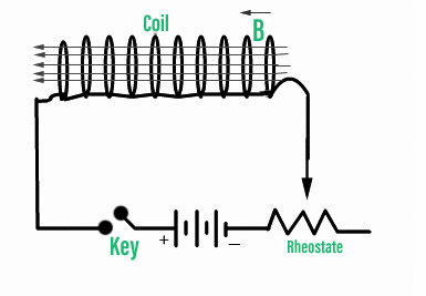
The battery will produce a constant current in the coil if the rheostat resistance is kept constant. A continuous magnetic field will be induced inside the coil due to the constant current provided to it.
As the resistance of the rheostat is changed, the current flowing through the coil will also change. Since the current is changing, they will be a changing magnetic flux inside the coil. Due to the effect of changing magnetic flux, an emf will be induced inside this coil, trying to oppose the magnetic flux. Hence, due to the induced emf, the direction of current induced will be opposite to that of current supplied.
The current flowing in the coil determines the flux induced in the coil: ϕ ∝ I As a result, the flux-to-current ratio must be constant, as this will define the coil’s capacity to create magnetic flux in relation to the current provided. Self-inductance is the name for this constant (L). L=ϕ/I An inductor is the result of this process. If there are N turns on the coil, then L=Nϕ/I Nϕ=LI Differentiating this equation in terms of time on both sides d/dt (Nϕ)=d/dt (LI) N dϕ/dt=L dI/dt But, according to Faraday’s law of EMI, emf induced in a coil is, ε=–N dϕ/dt The negative sign indicates that the induced emf is in the opposite direction of the present rate of change. ε=–L dI/dt L=–ε /dI/dt As a result, self-inductance may alternatively be defined as the emf induced per unit rate of current change within the coil minus the emf induced per unit rate of current change. The SI unit of inductance is: Wb/A=Vs/A=Henry (H)
Magnetic Energy Stored in an Inductor An inductor stores energy in the form of a magnetic field because it may induce its emf. Let us calculate the magnetic energy stored in an inductor using the following equation: The rate of work done for a current I in the circuit may be represented as: dW/dt=ε I Substituting the following equation for the coil’s induced emf: dW/dt=–L dI/dt I dW=–LI dI Integrating both sides of this equation: ∫dW=∫–LI dI W=–1/2 LI 2 Work done is the inverse of energy stored. So, if the inductor’s initial magnetic energy is zero, the energy stored in the inductor is: U = 1/2 LI 2
Mutual Inductance
Self-inductance is similar to mutual inductance. Instead, it consists of only two coils. One of them is given current, while the other is given emf.
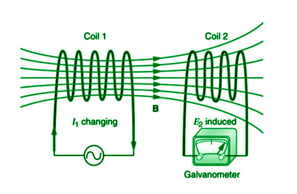
Coil-1 is linked to a supply and a rheostat in the diagram, whereas coil-2 is connected to a galvanometer. Coil-1 will begin to flow with a fluctuating current. It will be induced with a shifting magnetic flux as a result of this. Because the coils are so near together, the changing magnetic flux will be connected to the other. Because the magnetic flux through coil-2 is constantly changing with respect to time, an emf opposing this magnetic flux will be induced in coil-2, causing a current to flow in the opposite direction of the provided current. As a consequence, we may claim that the current delivered in coil-1 causes the flux via coil-2.
As a result, the flux through coil-2 and the current delivered in coil-1 will have a constant ratio. Mutual inductance in coil-2 owing to coil-1 is the name for this constant.
M 21 =ϕ 2 / I 1
We may define mutual inductance between two coils as the ratio of flux associated with one coil per unit current delivered in the other coil using the following equation.
ϕ 2 =M 21 I 1
Taking the preceding equation and differentiating it with regard to time
d/dt(ϕ 2 )=d/dt(M 21 I 1 )
Using Faraday’s law of EMI
ε 2 =–M 21 dI 1 /dt
M 21 =–ε 2 /dI 1 /dt
As a result, mutual inductance may alternatively be defined as the emf induced per unit rate of change in current in the inducing coil minus the emf induced per unit rate of change in current in the inducing coil.
Applications of Inductors
- Choking circuits mostly employ inductors (choke coil).
- In a transformer, the mutual inductance concept is applied.
- As the formula suggests, they are employed to store energy.
- To create alternating current, it’s used in an LC oscillator circuit.
- Used in power converters as well (ac-ac or dc-dc).
Sample Questions
Question 1: When a current of 2mA is supplied to a coil with 100 turns, a magnetic flux of magnitude 0.2Wb is linked with it. Find the self-inductance of this coil.
Current supplied to the coil I=2mA Number of turns in the coil (N)=100 Magnetic flux linked with the coil (ϕ)=0.2Wb Self-inductance of a coil is given by the equation L=Nϕ/I Substituting the values L=100×0.2/2 ∴ L=10H This coil has a self-inductance of 10H.
Question 2: Determine the energy stored in an inductor of inductance 100mH when a current of 0.2A is passed through it.
The inductance of the inductor (L)=100mH Current passed through it (I)=0.2A Energy stored in an inductor is given by the equation U=1/2LI 2 Substituting the values U=1/2×100×10 –3 ×0.2×0.2 ∴U=2mJ The energy stored in this coil is 2mJ.
Question 3: What is the principle of mutual induction?
Mutual induction is based on the electromagnetic induction concept. When one coil’s magnetic field connects to the other, the second coil generates its own emf. Mutual induction is the term for this procedure.
Question 4: Two long solenoids having length L and cross-sectional area A are placed in such a way that their axis coincide. Find the mutual inductance of this system.
A long solenoid’s magnetic field is provided by: B=μ0NI/L As a result, if electricity is delivered through one of the solenoids, the magnetic flux within it will be connected to the other. As a result, this system’s mutual induction will be: M=B 1 A/L ∴ M=μ 0 N 1 N 2 A/L
Question 5: What are the applications of inductors?
Inductors are commonly used in choking circuits (choke coil). The mutual inductance notion is used in transformers. They are used to store energy, as the formula says. It’s utilised in an LC oscillator circuit to generate alternating current. It’s also used in power converters (ac-ac or dc-dc).
Question 6: What is the use of mutual induction?
Mutual induction is used in transformers, generators, motors, etc.
Question 7: What is the use of Inductance?
Inductance is required to induce back emf and keep current flowing even after the switch is turned off.
Question 8: A long solenoid has 500 turns. When a current of 2 A is passed through it, the resulting magnetic flux linked with each turn of the solenoid is 4×10 −3 Wb. find self-inductance.
Φ=4×10 −3 Wb/turn N= Number of turns =500 I= Current flowing =2A N×Φ=L×I ∴500×4×10 −3 =L×2 ∴L= 500×4×10 −3 /2 ∴L=1H ∴ Self-inductance of solenoid is 1.0H
Question 9: A solenoid (air core) has 400 turns, is 20 cm long and has a cross-section of 4cm 2 . Then find the coefficient of self-induction.
n=400turns ,l=20cm ,A=4cm 2 L= 1⋅25×10 −6 Hm −1 ×400×400×4×100 / 100×100×20 =4×10 −4 H
Question 10: When a current of 4A between two coils changes to 12A in 0.5s in primary and induces an emf of 50mV in the secondary. Calculate the mutual inductance between the two coils.
M= e 2 / di 2 /dt =(50 x 10 -3 ) / (8/0.5) =3.125 x 10 -3 H =3.125 mH
Please Login to comment...
Similar reads.

- School Learning
- School Physics
- How to Use ChatGPT with Bing for Free?
- 7 Best Movavi Video Editor Alternatives in 2024
- How to Edit Comment on Instagram
- 10 Best AI Grammar Checkers and Rewording Tools
- 30 OOPs Interview Questions and Answers (2024)
Improve your Coding Skills with Practice
What kind of Experience do you want to share?
Problem Solving Techniques: Induction
Nicholas Miklaucic
2020-01-16 13:53
This is the second in my series on problem-solving techniques: for the first, see this post on invariants.
As I’ve previously discussed, I’m fascinated by the ability to create proofs or solutions for problems that are easy to understand but difficult to synthesize. In this series, I’m trying to shed some limited insight on how we mere mortals can arrive at these beautiful and creative insights.
Take the case of the structure of benzene. Chemists had been struggling to come up with a viable structure for \(C_6H_6\): the experimental results for the compound seemed to contradict their available theories. The scientist Friedrich August Kekulé finally theorized the correct solution problem by realizing that benzene was a ring structure, with the hydrogens on the outside and the carbons in a hexagonal configuration on the inside. (The actual work of proving this was done by Kathleen Londsdale in 1929.)
This story is a little dubious, and it certainly obscures the important study of resonance that actually makes the benzene structure work. (I’m not including an image of the actual structure because it isn’t quite what Kekulé thought it was, for example.) But it’s a really nice story, wouldn’t you agree?
Kekulé described the process by which he first realized benzene’s structure 25 years later. As the story goes, he fell asleep while thinking on the problem and had a vivid dream of the ouroboros : a snake eating its own tail. After waking, he realized that this ouroboros described the structure of benzene: a cycle. This structure, once you think to theorize it, instantly explains most of the issues that had confounded prior attempts to find the solution to the benzene problem.
The reason I’m talking about Kekulé is that our goal is to arrive at these kinds of solutions without metaphorical epiphanies from our subconscious. So, with this very long prologue out of the way, how does induction help us solve problems?
Let’s introduce the concept with an example problem.
The Blue-Eyed Islanders
Here’s our example logic problem:
200 people live on an island. All of them are perfect logicians: they instantly make any logically valid deduction the instant it is possible to do so. None of them know their own eye color: there are no mirrors or reflective surfaces, and it is forbidden to talk about eye color. They do know that only two eye colors exist on the island: blue, and green. In actuality, there are 100 blue-eyed and 100 green-eyed people on the island. Every islander sees the eye color of everyone else on the island. Each islander thus sees 99 people with their eye color and 100 people with the other eye color, but they can’t use this information to determine their own eye color because they don’t know the total numbers. Each day, a bus passes through the island, and anyone who knows their own eye color leaves. The residents of the island know exactly who leaves and when. They also know all of these rules. One day, as part of an ancient ritual, a wise man comes onto the island and is allowed to say one thing to the islanders. He pauses, and then says the following: “I see someone with blue eyes.” What can the islanders deduce from this? Who figures out their eye color and leaves, and when?
I’d encourage you to try and solve it on your own, of course. There’s no trickery: if you’re unsure of something, assume whatever makes the problem more interesting. (And the solution is not that nothing happens!)
This problem, at least to me, seems really hard. We’ll see, however, that there is a structured way of approaching this problem that doesn’t require anything of your subconscious!
The Principle of Mathematical Induction
This is one of the fancier sounding concepts in math, but it’s very simple. It’s essentially the following logical deduction:
Let’s say we have some statement \(X\) that’s dependent on a natural number \(n\). If:
- \(X\) is true for \(0\) (or sometimes \(1\))
- If \(X\) holds for \(n - 1\), it holds for \(n\)
Then \(X\) holds for all natural numbers.
The analogy I am legally required to make involves a domino chain. Induction is basically saying that if we knock over the first domino, and each domino knocks over the next one, then all of the dominos get knocked over.
There are some more complicated forms of induction, but this version is more than enough to solve a large amount of problems. I’ve presented it as a proof technique, but we can essentially think of it in a problem-solving context as well: when a problem depends on some large natural number \(N\), find the smallest number \(N\) could be that doesn’t completely trivialize the problem, think about that case, and then try to work upwards from there.
Solving the Blue-Eyed Islander Problem
OK , so how can we apply this to solve our problem? It’s really hard to reason about 200 people at once: let’s start with the smallest cases we can, try to establish a pattern, and go from there.
The problem requires at least one person to have blue eyes. So the absolute simplest case is a single islander with blue eyes. This is pretty boring: the wise man says that they see someone with blue eyes, and then the islander knows they have blue eyes and boards the next bus off the island.
Let’s try the next case: 2 people. Now we have two options: either both have blue eyes, or only one does. The case with 1 blue and 1 green is closer to our original problem, so we’ll try it first. Now, when they hear the wise man, the islander with blue eyes knows that they have blue eyes because they see the other person has green eyes. Thus, nothing changes: they still board the first bus home.
But now, we have a new complexity from 2 people that didn’t exist with one. On day 2, once the blue-eyed islander leaves, the green-eyed islander realizes that they must have green eyes. After all, if they had blue eyes, there’s no way the other islander would have known they had blue eyes. Thus, on day 2, the green-eyed islander leaves.
One of the best things about induction is that it lets you reduce problems to previously solved instances when you’re working through new versions of it, which greatly speeds up the process of deduction. We can see that with the case where there are 2 blue-eyed islanders. Each of them can’t leave the first day because they don’t know their own eye color. However , they make the same logical deductions we just made: both of them, on the second day, realize that if they had green eyes the other person would have already left the island. Thus, on the second day, both of them leave the island.
You might already see how this will play out, but let’s try the case for \(n = 3\). First, imagine the case with 1 blue-eyed person and 2 green-eyed people. Here, on day 1, the blue-eyed islander will deduce their eye color and leave, and on day 2 both of the green-eyed islanders leave: they know that the blue-eyed person could only have left if they saw only green eyes. If there are 2 blue-eyed people, then nothing will happen on day 1. On day 2, both of the blue-eyed islanders will know that they have blue eyes because otherwise the other blue-eyed person would have left on day 1, and so both of them will leave on day 2. The green-eyed islander, after seeing this, will leave on day 3. If all of them have blue eyes, then 2 days pass before anything happens. Then, because nothing happened on day 2, all of them can infer that they have blue eyes, and so they all leave on day 3.
This logic continues to hold up until \(n = 200\). In our version of the problem, the solution goes like this: for 99 days, nothing will happen, and then on day 100 all of the blue-eyed people will leave. Seeing this, all of the green-eyed islanders will know that there were 100 blue-eyed people in total, and so all of them will leave the next day.
There’s quite the elegance to this problem: figuring out what happens is very hard in the case that’s far removed from what we can easily deduce, but there’s a clear pattern that lets us build up our deductions until we get where we need to be. I hope it gives some indication of the usefulness of induction as a technique.
The Handy-Dandy Pollard’s Rho Guide to Using Induction
Just like the post on invariants, I want to give a “meta-solution” archetype for problems that can be applied when it’s useful to do so. This isn’t completely automatic, because of its generality, but it’s useful enough to guide you in a direction that’s likely to provide insights instead of waiting for a dream.
The first thing to know is when induction should be considered. Induction, in the form we’ve shown, requires some natural number \(n\) in the problem, such that \(n\) itself doesn’t qualitatively change the problem. (In the islander problem, each extra person with blue eyes simply adds another day that they all wait.) This can sometimes be pretty sneaky, as we’ll see. Secondly, the problem needs to have some sort of recursive structure: when we think of writing down a solution, we usually approach this by trying to solve the subsequent problem in terms of the one we just solved, but when we’re trying to figure out whether this is even worth trying we usually approach it by thinking “can this problem be decomposed into sub-problems?” Sometimes you need more than the immediately-preceding problem’s solution to get to the next one: that’s fine for induction! (It’s perfectly fine if you need the preceding three cases to get to the next one, for example.)
Once you’re convinced it’s worth trying, here’s my advice for doing so:
- Isolate the natural number \(n\) at the heart of the problem. Sometimes you have more than one choice: often all of them will work, but try whichever one seems easiest to break the problem down using.
- Work on the simplest meaningful case. For most problems this is \(n = 0\) or \(n = 1\).
- Once you’ve done the first case, increase \(n\) by one and keep going.
- Search for some way of reducing the problem to the one you just solved.
- Repeat steps 3 and 4 until you either find a pattern or give up.
A Harder Example
There’s a bit of a problem for me as I write this. Induction is far more straightforward to apply to problems than the concept of invariance: it’s pretty paint-by-numbers. That means that harder examples tend to really mean “way more tedious” and not “interesting to explain.” Things like Euler’s formula for graphs or Pick’s theorem are possible applications of induction proofs, but they aren’t really fun , just long to do properly and with mathematical rigor.
Basically, any time there are ways to prove something with induction and without it, the way without tends to be cooler. (This is definitely true for Euler’s formula: I may show a neat proof of that some other time.) It’s only for problems like our islander one where induction is the only method of showing the solution that it tends to feel elegant to use.
The other problem that I often see when induction is taught in math classes is that it’s used to prove completely nonobvious results! A lot of common summations, like the sum of the first \(n\) natural numbers being \(\frac{n(n+1)}{2}\), aren’t obvious when you don’t know them but can easily be proved through induction if you do. For example, the closed-form solution for the \(n\) th Fibonacci number \(F_n\), Binet’s formula , looks like this:
\[F_n = \frac{1}{\sqrt{5}}\left(\left(\frac{1 + \sqrt{5}}{2}\right)^n - \left(\frac{1 - \sqrt{5}}{2} \right)^n \right)\]
Telling someone to prove this with induction is just sad and demoralizing: it reduces the math student to a mere assistant who helps clean up the elegant work that other people did. The method by which you can solve general recurrences like the Fibonacci sequence is very interesting, but verifying the formula in a way that gives you absolutely no insight into why it’s true isn’t what math is about, in my book.
I’m going to instead present a more complicated example of induction where it’s used to solve a problem, not merely to write a proof.
For examples of induction in proofs, check out a helpful list of problems by Alexandersson here. Most of these are pretty rote (you’ll see Binet’s formula, for example), but there are some clever ones, including the problem I’ll be showing about tiling with L-shapes.
The example I’m going to use should be a little familiar to anyone who read my previous post on invariants. Is it possible to tile a \(2^n \times 2^n\) square with any one square removed using L-shaped pieces? (For the very elegant proof that this cannot be done with any 2 squares removed, see that post. You’ll notice that the argument I present there doesn’t generalize to this case, so you’ll have to figure it out on your own.)
I would highly encourage you to do this on your own if you’re trying to get better at solving problems with induction. This is a little more challenging than our last problem, because our natural number \(n\) is an exponent: every problem has four times as many squares as the previous iteration! I’ll go over the solution under the next header.
A Tiling Problem That Can Be Done?
OK , so let’s apply our little recipe of induction to this problem. The base case we’re going to use is \(n = 1\): \(n = 0\) sorta makes sense, but not really. A 2x2 square with one square removed is just one of the L-shapes we’re tiling with, so it’s a very simple base case.
For 4x4 squares, we could try and find a tiling on our own for every possible choice of the square to take away. But, instead, we’re going to try and base this on the previous case so we can save some time. This is where the magic happens.
Imagine cutting the grid by halves both ways, to split it into 4 copies of the previous iteration: 4 2x2 squares. Note that only one of these will have a square removed for now: we know by our previous case that whichever quadrant has that missing square can be tiled. Now we need to figure out how to deal with the other copies, all of which don’t have a missing square—yet. We can add a single L-shape in the very center such that it has one square in each of these three remaining quadrants. This removes one square from each of them, and so because the previous iteration was solved we know that each of the remaining quadrants can be tiled. Thus, the 4x4 square with one removed can be tiled with L-shaped pieces.
Of course, there’s nothing about this logic that doesn’t hold for the 8x8 case, the 16x16 case, and so on. Thus, by induction, we’ve shown that any \(2^n \times 2^n\) square can be tiled with L-shaped pieces.
Note that there’s something wonderfully constructive about this approach: we don’t just show that a tiling is possible, we show exactly how to do it. This is a strength of induction as a method: it tends to really show the relationships between subproblems, which often is very useful for constructing solutions.
Other Examples of Induction
Just like last time, I’ll try and very quickly go through some other common uses of induction in as many diverse fields as I can. This won’t be nearly as varied as the previous version of this for invariants, because that concept is far more general, but it’ll still, I hope, provide a good sense of when induction might be applicable to a problem.
Series and Sums
Any series with some closed-form sum over the natural numbers or some closed-form solution for a recursive function can usually be proven with induction, although as I griped earlier it’s not so easy to use induction to solve these series. However, if you notice a pattern, you can often use induction to prove it rigorously. Some common examples are the sums of squares, \(\sum_{i=1}^n i^2 = \frac{n(n+1)(2n+1)}{6}\), Binet’s formula which I showed above, and various combinatorics problems.
Graph Theory
Graph theory is a natural fit for induction: the number of vertices in a graph, the number of edges, and lots of other properties are all natural numbers. Induction on any one of these can be used to prove all sorts of theorems about graphs: you show that it holds for the base case and that it doesn’t change when you add a vertex or an edge. Examples are Euler’s formula, which I discussed earlier, or coloring theorems.
Number Theory
Number theory is usually slightly harder to make work with induction, because things like prime factorization change in incredibly complex ways when you add 1. But strong induction , where you don’t go back by 1 every step, is very useful. For example, proving that any number has a unique prime factorization can be done using induction.
That’s it for this post: I hope this helps any of you solving problems creatively using this technique. Stay tuned for more!

Free Mathematics Tutorials

Mathematical Induction - Problems With Solutions
Several problems with detailed solutions on mathematical induction are presented.
The principle of mathematical induction is used to prove that a given proposition (formula, equality, inequality…) is true for all positive integer numbers greater than or equal to some integer N. Let us denote the proposition in question by P (n), where n is a positive integer. The proof involves two steps: Step 1: We first establish that the proposition P (n) is true for the lowest possible value of the positive integer n. Step 2: We assume that P (k) is true and establish that P (k+1) is also true
Solution to Problem 3:
Statement P (n) is defined by 1 3 + 2 3 + 3 3 + ... + n 3 = n 2 (n + 1) 2 / 4 STEP 1: We first show that p (1) is true. Left Side = 1 3 = 1 Right Side = 1 2 (1 + 1) 2 / 4 = 1 hence p (1) is true. STEP 2: We now assume that p (k) is true 1 3 + 2 3 + 3 3 + ... + k 3 = k 2 (k + 1) 2 / 4 add (k + 1) 3 to both sides 1 3 + 2 3 + 3 3 + ... + k 3 + (k + 1) 3 = k 2 (k + 1) 2 / 4 + (k + 1) 3 factor (k + 1) 2 on the right side = (k + 1) 2 [ k 2 / 4 + (k + 1) ] set to common denominator and group = (k + 1) 2 [ k 2 + 4 k + 4 ] / 4 = (k + 1) 2 [ (k + 2) 2 ] / 4 We have started from the statement P(k) and have shown that 1 3 + 2 3 + 3 3 + ... + k 3 + (k + 1) 3 = (k + 1) 2 [ (k + 2) 2 ] / 4 Which is the statement P(k + 1).
Statement P (n) is defined by n 3 + 2 n is divisible by 3 STEP 1: We first show that p (1) is true. Let n = 1 and calculate n 3 + 2n 1 3 + 2(1) = 3 3 is divisible by 3 hence p (1) is true. STEP 2: We now assume that p (k) is true k 3 + 2 k is divisible by 3 is equivalent to k 3 + 2 k = 3 M , where M is a positive integer. We now consider the algebraic expression (k + 1) 3 + 2 (k + 1); expand it and group like terms (k + 1) 3 + 2 (k + 1) = k 3 + 3 k 2 + 5 k + 3 = [ k 3 + 2 k] + [3 k 2 + 3 k + 3] = 3 M + 3 [ k 2 + k + 1 ] = 3 [ M + k 2 + k + 1 ] Hence (k + 1) 3 + 2 (k + 1) is also divisible by 3 and therefore statement P(k + 1) is true.
Statement P (n) is defined by 3 n > n 2 STEP 1: We first show that p (1) is true. Let n = 1 and calculate 3 1 and 1 2 and compare them 3 1 = 3 1 2 = 1 3 is greater than 1 and hence p (1) is true. Let us also show that P(2) is true. 3 2 = 9 2 2 = 4 Hence P(2) is also true. STEP 2: We now assume that p (k) is true 3 k > k 2 Multiply both sides of the above inequality by 3 3 * 3 k > 3 * k 2 The left side is equal to 3 k + 1 . For k >, 2, we can write k 2 > 2 k and k 2 > 1 We now combine the above inequalities by adding the left hand sides and the right hand sides of the two inequalities 2 k 2 > 2 k + 1 We now add k 2 to both sides of the above inequality to obtain the inequality 3 k 2 > k 2 + 2 k + 1 Factor the right side we can write 3 * k 2 > (k + 1) 2 If 3 * 3 k > 3 * k 2 and 3 * k 2 > (k + 1) 2 then 3 * 3 k > (k + 1) 2 Rewrite the left side as 3 k + 1 3 k + 1 > (k + 1) 2 Which proves tha P(k + 1) is true
Statement P (n) is defined by n! > 2 n STEP 1: We first show that p (4) is true. Let n = 4 and calculate 4 ! and 2 n and compare them 4! = 24 2 4 = 16 24 is greater than 16 and hence p (4) is true. STEP 2: We now assume that p (k) is true k! > 2 k Multiply both sides of the above inequality by k + 1 k! (k + 1)> 2 k (k + 1) The left side is equal to (k + 1)!. For k >, 4, we can write k + 1 > 2 Multiply both sides of the above inequality by 2 k to obtain 2 k (k + 1) > 2 * 2 k The above inequality may be written 2 k (k + 1) > 2 k + 1 We have proved that (k + 1)! > 2 k (k + 1) and 2 k (k + 1) > 2 k + 1 we can now write (k + 1)! > 2 k + 1 We have assumed that statement P(k) is true and proved that statment P(k+1) is also true.
STEP 1: For n = 1 [ R (cos t + i sin t) ] 1 = R 1 (cos 1*t + i sin 1*t) It can easily be seen that the two sides are equal. STEP 2: We now assume that the theorem is true for n = k, hence [ R (cos t + i sin t) ] k = R k (cos kt + i sin kt) Multiply both sides of the above equation by R (cos t + i sin t) [ R (cos t + i sin t) ] k R (cos t + i sin t) = R k (cos kt + i sin kt) R (cos t + i sin t) Rewrite the above as follows [ R (cos t + i sin t) ] k + 1 = R k + 1 [ (cos kt cos t - sin kt sin t) + i (sin kt cos t + cos kt sin t) ] Trigonometric identities can be used to write the trigonometric expressions (cos kt cos t - sin kt sin t) and (sin kt cos t + cos kt sin t) as follows (cos kt cos t - sin kt sin t) = cos(kt + t) = cos(k + 1)t (sin kt cos t + cos kt sin t) = sin(kt + t) = sin(k + 1)t Substitute the above into the last equation to obtain [ R (cos t + i sin t) ] k + 1 = R k + 1 [ cos (k + 1)t + sin(k + 1)t ] It has been established that the theorem is true for n = 1 and that if it assumed true for n = k it is true for n = k + 1.
More References and links
Popular pages.
- Math Problems, Questions and Online Self Tests
- File Not Found
- Geometric Sequences Problems with Solutions
- Questions on Functions with Solutions
- Arithmetic Sequences Problems with Solutions
Stay In Touch
- Privacy Policy
Thank you for visiting nature.com. You are using a browser version with limited support for CSS. To obtain the best experience, we recommend you use a more up to date browser (or turn off compatibility mode in Internet Explorer). In the meantime, to ensure continued support, we are displaying the site without styles and JavaScript.
- View all journals
- My Account Login
- Explore content
- About the journal
- Publish with us
- Sign up for alerts
- Open access
- Published: 10 April 2024
A hybrid particle swarm optimization algorithm for solving engineering problem
- Jinwei Qiao 1 , 2 ,
- Guangyuan Wang 1 , 2 ,
- Zhi Yang 1 , 2 ,
- Xiaochuan Luo 3 ,
- Jun Chen 1 , 2 ,
- Kan Li 4 &
- Pengbo Liu 1 , 2
Scientific Reports volume 14 , Article number: 8357 ( 2024 ) Cite this article
Metrics details
- Computational science
- Mechanical engineering
To overcome the disadvantages of premature convergence and easy trapping into local optimum solutions, this paper proposes an improved particle swarm optimization algorithm (named NDWPSO algorithm) based on multiple hybrid strategies. Firstly, the elite opposition-based learning method is utilized to initialize the particle position matrix. Secondly, the dynamic inertial weight parameters are given to improve the global search speed in the early iterative phase. Thirdly, a new local optimal jump-out strategy is proposed to overcome the "premature" problem. Finally, the algorithm applies the spiral shrinkage search strategy from the whale optimization algorithm (WOA) and the Differential Evolution (DE) mutation strategy in the later iteration to accelerate the convergence speed. The NDWPSO is further compared with other 8 well-known nature-inspired algorithms (3 PSO variants and 5 other intelligent algorithms) on 23 benchmark test functions and three practical engineering problems. Simulation results prove that the NDWPSO algorithm obtains better results for all 49 sets of data than the other 3 PSO variants. Compared with 5 other intelligent algorithms, the NDWPSO obtains 69.2%, 84.6%, and 84.6% of the best results for the benchmark function ( \({f}_{1}-{f}_{13}\) ) with 3 kinds of dimensional spaces (Dim = 30,50,100) and 80% of the best optimal solutions for 10 fixed-multimodal benchmark functions. Also, the best design solutions are obtained by NDWPSO for all 3 classical practical engineering problems.
Introduction
In the ever-changing society, new optimization problems arise every moment, and they are distributed in various fields, such as automation control 1 , statistical physics 2 , security prevention and temperature prediction 3 , artificial intelligence 4 , and telecommunication technology 5 . Faced with a constant stream of practical engineering optimization problems, traditional solution methods gradually lose their efficiency and convenience, making it more and more expensive to solve the problems. Therefore, researchers have developed many metaheuristic algorithms and successfully applied them to the solution of optimization problems. Among them, Particle swarm optimization (PSO) algorithm 6 is one of the most widely used swarm intelligence algorithms.
However, the basic PSO has a simple operating principle and solves problems with high efficiency and good computational performance, but it suffers from the disadvantages of easily trapping in local optima and premature convergence. To improve the overall performance of the particle swarm algorithm, an improved particle swarm optimization algorithm is proposed by the multiple hybrid strategy in this paper. The improved PSO incorporates the search ideas of other intelligent algorithms (DE, WOA), so the improved algorithm proposed in this paper is named NDWPSO. The main improvement schemes are divided into the following 4 points: Firstly, a strategy of elite opposition-based learning is introduced into the particle population position initialization. A high-quality initialization matrix of population position can improve the convergence speed of the algorithm. Secondly, a dynamic weight methodology is adopted for the acceleration coefficients by combining the iterative map and linearly transformed method. This method utilizes the chaotic nature of the mapping function, the fast convergence capability of the dynamic weighting scheme, and the time-varying property of the acceleration coefficients. Thus, the global search and local search of the algorithm are balanced and the global search speed of the population is improved. Thirdly, a determination mechanism is set up to detect whether the algorithm falls into a local optimum. When the algorithm is “premature”, the population resets 40% of the position information to overcome the local optimum. Finally, the spiral shrinking mechanism combined with the DE/best/2 position mutation is used in the later iteration, which further improves the solution accuracy.
The structure of the paper is given as follows: Sect. “ Particle swarm optimization (PSO) ” describes the principle of the particle swarm algorithm. Section “ Improved particle swarm optimization algorithm ” shows the detailed improvement strategy and a comparison experiment of inertia weight is set up for the proposed NDWPSO. Section “ Experiment and discussion ” includes the experimental and result discussion sections on the performance of the improved algorithm. Section “ Conclusions and future works ” summarizes the main findings of this study.
Literature review
This section reviews some metaheuristic algorithms and other improved PSO algorithms. A simple discussion about recently proposed research studies is given.
Metaheuristic algorithms
A series of metaheuristic algorithms have been proposed in recent years by using various innovative approaches. For instance, Lin et al. 7 proposed a novel artificial bee colony algorithm (ABCLGII) in 2018 and compared ABCLGII with other outstanding ABC variants on 52 frequently used test functions. Abed-alguni et al. 8 proposed an exploratory cuckoo search (ECS) algorithm in 2021 and carried out several experiments to investigate the performance of ECS by 14 benchmark functions. Brajević 9 presented a novel shuffle-based artificial bee colony (SB-ABC) algorithm for solving integer programming and minimax problems in 2021. The experiments are tested on 7 integer programming problems and 10 minimax problems. In 2022, Khan et al. 10 proposed a non-deterministic meta-heuristic algorithm called Non-linear Activated Beetle Antennae Search (NABAS) for a non-convex tax-aware portfolio selection problem. Brajević et al. 11 proposed a hybridization of the sine cosine algorithm (HSCA) in 2022 to solve 15 complex structural and mechanical engineering design optimization problems. Abed-Alguni et al. 12 proposed an improved Salp Swarm Algorithm (ISSA) in 2022 for single-objective continuous optimization problems. A set of 14 standard benchmark functions was used to evaluate the performance of ISSA. In 2023, Nadimi et al. 13 proposed a binary starling murmuration optimization (BSMO) to select the effective features from different important diseases. In the same year, Nadimi et al. 14 systematically reviewed the last 5 years' developments of WOA and made a critical analysis of those WOA variants. In 2024, Fatahi et al. 15 proposed an Improved Binary Quantum-based Avian Navigation Optimizer Algorithm (IBQANA) for the Feature Subset Selection problem in the medical area. Experimental evaluation on 12 medical datasets demonstrates that IBQANA outperforms 7 established algorithms. Abed-alguni et al. 16 proposed an Improved Binary DJaya Algorithm (IBJA) to solve the Feature Selection problem in 2024. The IBJA’s performance was compared against 4 ML classifiers and 10 efficient optimization algorithms.
Improved PSO algorithms
Many researchers have constantly proposed some improved PSO algorithms to solve engineering problems in different fields. For instance, Yeh 17 proposed an improved particle swarm algorithm, which combines a new self-boundary search and a bivariate update mechanism, to solve the reliability redundancy allocation problem (RRAP) problem. Solomon et al. 18 designed a collaborative multi-group particle swarm algorithm with high parallelism that was used to test the adaptability of Graphics Processing Units (GPUs) in distributed computing environments. Mukhopadhyay and Banerjee 19 proposed a chaotic multi-group particle swarm optimization (CMS-PSO) to estimate the unknown parameters of an autonomous chaotic laser system. Duan et al. 20 designed an improved particle swarm algorithm with nonlinear adjustment of inertia weights to improve the coupling accuracy between laser diodes and single-mode fibers. Sun et al. 21 proposed a particle swarm optimization algorithm combined with non-Gaussian stochastic distribution for the optimal design of wind turbine blades. Based on a multiple swarm scheme, Liu et al. 22 proposed an improved particle swarm optimization algorithm to predict the temperatures of steel billets for the reheating furnace. In 2022, Gad 23 analyzed the existing 2140 papers on Swarm Intelligence between 2017 and 2019 and pointed out that the PSO algorithm still needs further research. In general, the improved methods can be classified into four categories:
Adjusting the distribution of algorithm parameters. Feng et al. 24 used a nonlinear adaptive method on inertia weights to balance local and global search and introduced asynchronously varying acceleration coefficients.
Changing the updating formula of the particle swarm position. Both papers 25 and 26 used chaotic mapping functions to update the inertia weight parameters and combined them with a dynamic weighting strategy to update the particle swarm positions. This improved approach enables the particle swarm algorithm to be equipped with fast convergence of performance.
The initialization of the swarm. Alsaidy and Abbood proposed 27 a hybrid task scheduling algorithm that replaced the random initialization of the meta-heuristic algorithm with the heuristic algorithms MCT-PSO and LJFP-PSO.
Combining with other intelligent algorithms: Liu et al. 28 introduced the differential evolution (DE) algorithm into PSO to increase the particle swarm as diversity and reduce the probability of the population falling into local optimum.
Particle swarm optimization (PSO)
The particle swarm optimization algorithm is a population intelligence algorithm for solving continuous and discrete optimization problems. It originated from the social behavior of individuals in bird and fish flocks 6 . The core of the PSO algorithm is that an individual particle identifies potential solutions by flight in a defined constraint space adjusts its exploration direction to approach the global optimal solution based on the shared information among the group, and finally solves the optimization problem. Each particle \(i\) includes two attributes: velocity vector \({V}_{i}=\left[{v}_{i1},{v}_{i2},{v}_{i3},{...,v}_{ij},{...,v}_{iD},\right]\) and position vector \({X}_{i}=[{x}_{i1},{x}_{i2},{x}_{i3},...,{x}_{ij},...,{x}_{iD}]\) . The velocity vector is used to modify the motion path of the swarm; the position vector represents a potential solution for the optimization problem. Here, \(j=\mathrm{1,2},\dots ,D\) , \(D\) represents the dimension of the constraint space. The equations for updating the velocity and position of the particle swarm are shown in Eqs. ( 1 ) and ( 2 ).
Here \({Pbest}_{i}^{k}\) represents the previous optimal position of the particle \(i\) , and \({Gbest}\) is the optimal position discovered by the whole population. \(i=\mathrm{1,2},\dots ,n\) , \(n\) denotes the size of the particle swarm. \({c}_{1}\) and \({c}_{2}\) are the acceleration constants, which are used to adjust the search step of the particle 29 . \({r}_{1}\) and \({r}_{2}\) are two random uniform values distributed in the range \([\mathrm{0,1}]\) , which are used to improve the randomness of the particle search. \(\omega\) inertia weight parameter, which is used to adjust the scale of the search range of the particle swarm 30 . The basic PSO sets the inertia weight parameter as a time-varying parameter to balance global exploration and local seeking. The updated equation of the inertia weight parameter is given as follows:
where \({\omega }_{max}\) and \({\omega }_{min}\) represent the upper and lower limits of the range of inertia weight parameter. \(k\) and \(Mk\) are the current iteration and maximum iteration.
Improved particle swarm optimization algorithm
According to the no free lunch theory 31 , it is known that no algorithm can solve every practical problem with high quality and efficiency for increasingly complex and diverse optimization problems. In this section, several improvement strategies are proposed to improve the search efficiency and overcome this shortcoming of the basic PSO algorithm.
Improvement strategies
The optimization strategies of the improved PSO algorithm are shown as follows:
The inertia weight parameter is updated by an improved chaotic variables method instead of a linear decreasing strategy. Chaotic mapping performs the whole search at a higher speed and is more resistant to falling into local optimal than the probability-dependent random search 32 . However, the population may result in that particles can easily fly out of the global optimum boundary. To ensure that the population can converge to the global optimum, an improved Iterative mapping is adopted and shown as follows:
Here \({\omega }_{k}\) is the inertia weight parameter in the iteration \(k\) , \(b\) is the control parameter in the range \([\mathrm{0,1}]\) .
The acceleration coefficients are updated by the linear transformation. \({c}_{1}\) and \({c}_{2}\) represent the influential coefficients of the particles by their own and population information, respectively. To improve the search performance of the population, \({c}_{1}\) and \({c}_{2}\) are changed from fixed values to time-varying parameter parameters, that are updated by linear transformation with the number of iterations:
where \({c}_{max}\) and \({c}_{min}\) are the maximum and minimum values of acceleration coefficients, respectively.
The initialization scheme is determined by elite opposition-based learning . The high-quality initial population will accelerate the solution speed of the algorithm and improve the accuracy of the optimal solution. Thus, the elite backward learning strategy 33 is introduced to generate the position matrix of the initial population. Suppose the elite individual of the population is \({X}=[{x}_{1},{x}_{2},{x}_{3},...,{x}_{j},...,{x}_{D}]\) , and the elite opposition-based solution of \(X\) is \({X}_{o}=[{x}_{{\text{o}}1},{x}_{{\text{o}}2},{x}_{{\text{o}}3},...,{x}_{oj},...,{x}_{oD}]\) . The formula for the elite opposition-based solution is as follows:
where \({k}_{r}\) is the random value in the range \((\mathrm{0,1})\) . \({ux}_{oij}\) and \({lx}_{oij}\) are dynamic boundaries of the elite opposition-based solution in \(j\) dimensional variables. The advantage of dynamic boundary is to reduce the exploration space of particles, which is beneficial to the convergence of the algorithm. When the elite opposition-based solution is out of bounds, the out-of-bounds processing is performed. The equation is given as follows:
After calculating the fitness function values of the elite solution and the elite opposition-based solution, respectively, \(n\) high quality solutions were selected to form a new initial population position matrix.
The position updating Eq. ( 2 ) is modified based on the strategy of dynamic weight. To improve the speed of the global search of the population, the strategy of dynamic weight from the artificial bee colony algorithm 34 is introduced to enhance the computational performance. The new position updating equation is shown as follows:
Here \(\rho\) is the random value in the range \((\mathrm{0,1})\) . \(\psi\) represents the acceleration coefficient and \({\omega }{\prime}\) is the dynamic weight coefficient. The updated equations of the above parameters are as follows:
where \(f(i)\) denotes the fitness function value of individual particle \(i\) and u is the average of the population fitness function values in the current iteration. The Eqs. ( 11 , 12 ) are introduced into the position updating equation. And they can attract the particle towards positions of the best-so-far solution in the search space.
New local optimal jump-out strategy is added for escaping from the local optimal. When the value of the fitness function for the population optimal particles does not change in M iterations, the algorithm determines that the population falls into a local optimal. The scheme in which the population jumps out of the local optimum is to reset the position information of the 40% of individuals within the population, in other words, to randomly generate the position vector in the search space. M is set to 5% of the maximum number of iterations.
New spiral update search strategy is added after the local optimal jump-out strategy. Since the whale optimization algorithm (WOA) was good at exploring the local search space 35 , the spiral update search strategy in the WOA 36 is introduced to update the position of the particles after the swarm jumps out of local optimal. The equation for the spiral update is as follows:
Here \(D=\left|{x}_{i}\left(k\right)-Gbest\right|\) denotes the distance between the particle itself and the global optimal solution so far. \(B\) is the constant that defines the shape of the logarithmic spiral. \(l\) is the random value in \([-\mathrm{1,1}]\) . \(l\) represents the distance between the newly generated particle and the global optimal position, \(l=-1\) means the closest distance, while \(l=1\) means the farthest distance, and the meaning of this parameter can be directly observed by Fig. 1 .
Spiral updating position.
The DE/best/2 mutation strategy is introduced to form the mutant particle. 4 individuals in the population are randomly selected that differ from the current particle, then the vector difference between them is rescaled, and the difference vector is combined with the global optimal position to form the mutant particle. The equation for mutation of particle position is shown as follows:
where \({x}^{*}\) is the mutated particle, \(F\) is the scale factor of mutation, \({r}_{1}\) , \({r}_{2}\) , \({r}_{3}\) , \({r}_{4}\) are random integer values in \((0,n]\) and not equal to \(i\) , respectively. Specific particles are selected for mutation with the screening conditions as follows:
where \(Cr\) represents the probability of mutation, \(rand\left(\mathrm{0,1}\right)\) is a random number in \(\left(\mathrm{0,1}\right)\) , and \({i}_{rand}\) is a random integer value in \((0,n]\) .
The improved PSO incorporates the search ideas of other intelligent algorithms (DE, WOA), so the improved algorithm proposed in this paper is named NDWPSO. The pseudo-code for the NDWPSO algorithm is given as follows:
The main procedure of NDWPSO.
Comparing the distribution of inertia weight parameters
There are several improved PSO algorithms (such as CDWPSO 25 , and SDWPSO 26 ) that adopt the dynamic weighted particle position update strategy as their improvement strategy. The updated equations of the CDWPSO and the SDWPSO algorithm for the inertia weight parameters are given as follows:
where \({\text{A}}\) is a value in \((\mathrm{0,1}]\) . \({r}_{max}\) and \({r}_{min}\) are the upper and lower limits of the fluctuation range of the inertia weight parameters, \(k\) is the current number of algorithm iterations, and \(Mk\) denotes the maximum number of iterations.
Considering that the update method of inertia weight parameters by our proposed NDWPSO is comparable to the CDWPSO, and SDWPSO, a comparison experiment for the distribution of inertia weight parameters is set up in this section. The maximum number of iterations in the experiment is \(Mk=500\) . The distributions of CDWPSO, SDWPSO, and NDWPSO inertia weights are shown sequentially in Fig. 2 .

The inertial weight distribution of CDWPSO, SDWPSO, and NDWPSO.
In Fig. 2 , the inertia weight value of CDWPSO is a random value in (0,1]. It may make individual particles fly out of the range in the late iteration of the algorithm. Similarly, the inertia weight value of SDWPSO is a value that tends to zero infinitely, so that the swarm no longer can fly in the search space, making the algorithm extremely easy to fall into the local optimal value. On the other hand, the distribution of the inertia weights of the NDWPSO forms a gentle slope by two curves. Thus, the swarm can faster lock the global optimum range in the early iterations and locate the global optimal more precisely in the late iterations. The reason is that the inertia weight values between two adjacent iterations are inversely proportional to each other. Besides, the time-varying part of the inertial weight within NDWPSO is designed to reduce the chaos characteristic of the parameters. The inertia weight value of NDWPSO avoids the disadvantages of the above two schemes, so its design is more reasonable.
Experiment and discussion
In this section, three experiments are set up to evaluate the performance of NDWPSO: (1) the experiment of 23 classical functions 37 between NDWPSO and three particle swarm algorithms (PSO 6 , CDWPSO 25 , SDWPSO 26 ); (2) the experiment of benchmark test functions between NDWPSO and other intelligent algorithms (Whale Optimization Algorithm (WOA) 36 , Harris Hawk Algorithm (HHO) 38 , Gray Wolf Optimization Algorithm (GWO) 39 , Archimedes Algorithm (AOA) 40 , Equilibrium Optimizer (EO) 41 and Differential Evolution (DE) 42 ); (3) the experiment for solving three real engineering problems (welded beam design 43 , pressure vessel design 44 , and three-bar truss design 38 ). All experiments are run on a computer with Intel i5-11400F GPU, 2.60 GHz, 16 GB RAM, and the code is written with MATLAB R2017b.
The benchmark test functions are 23 classical functions, which consist of indefinite unimodal (F1–F7), indefinite dimensional multimodal functions (F8–F13), and fixed-dimensional multimodal functions (F14–F23). The unimodal benchmark function is used to evaluate the global search performance of different algorithms, while the multimodal benchmark function reflects the ability of the algorithm to escape from the local optimal. The mathematical equations of the benchmark functions are shown and found as Supplementary Tables S1 – S3 online.
Experiments on benchmark functions between NDWPSO, and other PSO variants
The purpose of the experiment is to show the performance advantages of the NDWPSO algorithm. Here, the dimensions and corresponding population sizes of 13 benchmark functions (7 unimodal and 6 multimodal) are set to (30, 40), (50, 70), and (100, 130). The population size of 10 fixed multimodal functions is set to 40. Each algorithm is repeated 30 times independently, and the maximum number of iterations is 200. The performance of the algorithm is measured by the mean and the standard deviation (SD) of the results for different benchmark functions. The parameters of the NDWPSO are set as: \({[{\omega }_{min},\omega }_{max}]=[\mathrm{0.4,0.9}]\) , \(\left[{c}_{max},{c}_{min}\right]=\left[\mathrm{2.5,1.5}\right],{V}_{max}=0.1,b={e}^{-50}, M=0.05\times Mk, B=1,F=0.7, Cr=0.9.\) And, \(A={\omega }_{max}\) for CDWPSO; \({[r}_{max},{r}_{min}]=[\mathrm{4,0}]\) for SDWPSO.
Besides, the experimental data are retained to two decimal places, but some experimental data will increase the number of retained data to pursue more accuracy in comparison. The best results in each group of experiments will be displayed in bold font. The experimental data is set to 0 if the value is below 10 –323 . The experimental parameter settings in this paper are different from the references (PSO 6 , CDWPSO 25 , SDWPSO 26 , so the final experimental data differ from the ones within the reference.
As shown in Tables 1 and 2 , the NDWPSO algorithm obtains better results for all 49 sets of data than other PSO variants, which include not only 13 indefinite-dimensional benchmark functions and 10 fixed-multimodal benchmark functions. Remarkably, the SDWPSO algorithm obtains the same accuracy of calculation as NDWPSO for both unimodal functions f 1 –f 4 and multimodal functions f 9 –f 11 . The solution accuracy of NDWPSO is higher than that of other PSO variants for fixed-multimodal benchmark functions f 14 -f 23 . The conclusion can be drawn that the NDWPSO has excellent global search capability, local search capability, and the capability for escaping the local optimal.
In addition, the convergence curves of the 23 benchmark functions are shown in Figs. 3 , 4 , 5 , 6 , 7 , 8 , 9 , 10 , 11 , 12 , 13 , 14 , 15 , 16 , 17 , 18 and 19 . The NDWPSO algorithm has a faster convergence speed in the early stage of the search for processing functions f1-f6, f8-f14, f16, f17, and finds the global optimal solution with a smaller number of iterations. In the remaining benchmark function experiments, the NDWPSO algorithm shows no outstanding performance for convergence speed in the early iterations. There are two reasons of no outstanding performance in the early iterations. On one hand, the fixed-multimodal benchmark function has many disturbances and local optimal solutions in the whole search space. on the other hand, the initialization scheme based on elite opposition-based learning is still stochastic, which leads to the initial position far from the global optimal solution. The inertia weight based on chaotic mapping and the strategy of spiral updating can significantly improve the convergence speed and computational accuracy of the algorithm in the late search stage. Finally, the NDWPSO algorithm can find better solutions than other algorithms in the middle and late stages of the search.
Evolution curve of NDWPSO and other PSO algorithms for f1 (Dim = 30,50,100).
Evolution curve of NDWPSO and other PSO algorithms for f2 (Dim = 30,50,100).
Evolution curve of NDWPSO and other PSO algorithms for f3 (Dim = 30,50,100).
Evolution curve of NDWPSO and other PSO algorithms for f4 (Dim = 30,50,100).
Evolution curve of NDWPSO and other PSO algorithms for f5 (Dim = 30,50,100).
Evolution curve of NDWPSO and other PSO algorithms for f6 (Dim = 30,50,100).
Evolution curve of NDWPSO and other PSO algorithms for f7 (Dim = 30,50,100).
Evolution curve of NDWPSO and other PSO algorithms for f8 (Dim = 30,50,100).
Evolution curve of NDWPSO and other PSO algorithms for f9 (Dim = 30,50,100).
Evolution curve of NDWPSO and other PSO algorithms for f10 (Dim = 30,50,100).
Evolution curve of NDWPSO and other PSO algorithms for f11(Dim = 30,50,100).
Evolution curve of NDWPSO and other PSO algorithms for f12 (Dim = 30,50,100).
Evolution curve of NDWPSO and other PSO algorithms for f13 (Dim = 30,50,100).
Evolution curve of NDWPSO and other PSO algorithms for f14, f15, f16.
Evolution curve of NDWPSO and other PSO algorithms for f17, f18, f19.
Evolution curve of NDWPSO and other PSO algorithms for f20, f21, f22.
Evolution curve of NDWPSO and other PSO algorithms for f23.
To evaluate the performance of different PSO algorithms, a statistical test is conducted. Due to the stochastic nature of the meta-heuristics, it is not enough to compare algorithms based on only the mean and standard deviation values. The optimization results cannot be assumed to obey the normal distribution; thus, it is necessary to judge whether the results of the algorithms differ from each other in a statistically significant way. Here, the Wilcoxon non-parametric statistical test 45 is used to obtain a parameter called p -value to verify whether two sets of solutions are different to a statistically significant extent or not. Generally, it is considered that p ≤ 0.5 can be considered as a statistically significant superiority of the results. The p -values calculated in Wilcoxon’s rank-sum test comparing NDWPSO and other PSO algorithms are listed in Table 3 for all benchmark functions. The p -values in Table 3 additionally present the superiority of the NDWPSO because all of the p -values are much smaller than 0.5.
In general, the NDWPSO has the fastest convergence rate when finding the global optimum from Figs. 3 , 4 , 5 , 6 , 7 , 8 , 9 , 10 , 11 , 12 , 13 , 14 , 15 , 16 , 17 , 18 and 19 , and thus we can conclude that the NDWPSO is superior to the other PSO variants during the process of optimization.
Comparison experiments between NDWPSO and other intelligent algorithms
Experiments are conducted to compare NDWPSO with several other intelligent algorithms (WOA, HHO, GWO, AOA, EO and DE). The experimental object is 23 benchmark functions, and the experimental parameters of the NDWPSO algorithm are set the same as in Experiment 4.1. The maximum number of iterations of the experiment is increased to 2000 to fully demonstrate the performance of each algorithm. Each algorithm is repeated 30 times individually. The parameters of the relevant intelligent algorithms in the experiments are set as shown in Table 4 . To ensure the fairness of the algorithm comparison, all parameters are concerning the original parameters in the relevant algorithm literature. The experimental results are shown in Tables 5 , 6 , 7 and 8 and Figs. 20 , 21 , 22 , 23 , 24 , 25 , 26 , 27 , 28 , 29 , 30 , 31 , 32 , 33 , 34 , 35 and 36 .
Evolution curve of NDWPSO and other algorithms for f1 (Dim = 30,50,100).
Evolution curve of NDWPSO and other algorithms for f2 (Dim = 30,50,100).
Evolution curve of NDWPSO and other algorithms for f3(Dim = 30,50,100).
Evolution curve of NDWPSO and other algorithms for f4 (Dim = 30,50,100).
Evolution curve of NDWPSO and other algorithms for f5 (Dim = 30,50,100).
Evolution curve of NDWPSO and other algorithms for f6 (Dim = 30,50,100).
Evolution curve of NDWPSO and other algorithms for f7 (Dim = 30,50,100).
Evolution curve of NDWPSO and other algorithms for f8 (Dim = 30,50,100).
Evolution curve of NDWPSO and other algorithms for f9(Dim = 30,50,100).
Evolution curve of NDWPSO and other algorithms for f10 (Dim = 30,50,100).
Evolution curve of NDWPSO and other algorithms for f11 (Dim = 30,50,100).
Evolution curve of NDWPSO and other algorithms for f12 (Dim = 30,50,100).
Evolution curve of NDWPSO and other algorithms for f13 (Dim = 30,50,100).
Evolution curve of NDWPSO and other algorithms for f14, f15, f16.
Evolution curve of NDWPSO and other algorithms for f17, f18, f19.
Evolution curve of NDWPSO and other algorithms for f20, f21, f22.
Evolution curve of NDWPSO and other algorithms for f23.
The experimental data of NDWPSO and other intelligent algorithms for handling 30, 50, and 100-dimensional benchmark functions ( \({f}_{1}-{f}_{13}\) ) are recorded in Tables 8 , 9 and 10 , respectively. The comparison data of fixed-multimodal benchmark tests ( \({f}_{14}-{f}_{23}\) ) are recorded in Table 11 . According to the data in Tables 5 , 6 and 7 , the NDWPSO algorithm obtains 69.2%, 84.6%, and 84.6% of the best results for the benchmark function ( \({f}_{1}-{f}_{13}\) ) in the search space of three dimensions (Dim = 30, 50, 100), respectively. In Table 8 , the NDWPSO algorithm obtains 80% of the optimal solutions in 10 fixed-multimodal benchmark functions.
The convergence curves of each algorithm are shown in Figs. 20 , 21 , 22 , 23 , 24 , 25 , 26 , 27 , 28 , 29 , 30 , 31 , 32 , 33 , 34 , 35 and 36 . The NDWPSO algorithm demonstrates two convergence behaviors when calculating the benchmark functions in 30, 50, and 100-dimensional search spaces. The first behavior is the fast convergence of NDWPSO with a small number of iterations at the beginning of the search. The reason is that the Iterative-mapping strategy and the position update scheme of dynamic weighting are used in the NDWPSO algorithm. This scheme can quickly target the region in the search space where the global optimum is located, and then precisely lock the optimal solution. When NDWPSO processes the functions \({f}_{1}-{f}_{4}\) , and \({f}_{9}-{f}_{11}\) , the behavior can be reflected in the convergence trend of their corresponding curves. The second behavior is that NDWPSO gradually improves the convergence accuracy and rapidly approaches the global optimal in the middle and late stages of the iteration. The NDWPSO algorithm fails to converge quickly in the early iterations, which is possible to prevent the swarm from falling into a local optimal. The behavior can be demonstrated by the convergence trend of the curves when NDWPSO handles the functions \({f}_{6}\) , \({f}_{12}\) , and \({f}_{13}\) , and it also shows that the NDWPSO algorithm has an excellent ability of local search.
Combining the experimental data with the convergence curves, it is concluded that the NDWPSO algorithm has a faster convergence speed, so the effectiveness and global convergence of the NDWPSO algorithm are more outstanding than other intelligent algorithms.
Experiments on classical engineering problems
Three constrained classical engineering design problems (welded beam design, pressure vessel design 43 , and three-bar truss design 38 ) are used to evaluate the NDWPSO algorithm. The experiments are the NDWPSO algorithm and 5 other intelligent algorithms (WOA 36 , HHO, GWO, AOA, EO 41 ). Each algorithm is provided with the maximum number of iterations and population size ( \({\text{Mk}}=500,\mathrm{ n}=40\) ), and then repeats 30 times, independently. The parameters of the algorithms are set the same as in Table 4 . The experimental results of three engineering design problems are recorded in Tables 9 , 10 and 11 in turn. The result data is the average value of the solved data.
Welded beam design
The target of the welded beam design problem is to find the optimal manufacturing cost for the welded beam with the constraints, as shown in Fig. 37 . The constraints are the thickness of the weld seam ( \({\text{h}}\) ), the length of the clamped bar ( \({\text{l}}\) ), the height of the bar ( \({\text{t}}\) ) and the thickness of the bar ( \({\text{b}}\) ). The mathematical formulation of the optimization problem is given as follows:

Welded beam design.
In Table 9 , the NDWPSO, GWO, and EO algorithms obtain the best optimal cost. Besides, the standard deviation (SD) of t NDWPSO is the lowest, which means it has very good results in solving the welded beam design problem.
Pressure vessel design
Kannan and Kramer 43 proposed the pressure vessel design problem as shown in Fig. 38 to minimize the total cost, including the cost of material, forming, and welding. There are four design optimized objects: the thickness of the shell \({T}_{s}\) ; the thickness of the head \({T}_{h}\) ; the inner radius \({\text{R}}\) ; the length of the cylindrical section without considering the head \({\text{L}}\) . The problem includes the objective function and constraints as follows:

Pressure vessel design.
The results in Table 10 show that the NDWPSO algorithm obtains the lowest optimal cost with the same constraints and has the lowest standard deviation compared with other algorithms, which again proves the good performance of NDWPSO in terms of solution accuracy.
Three-bar truss design
This structural design problem 44 is one of the most widely-used case studies as shown in Fig. 39 . There are two main design parameters: the area of the bar1 and 3 ( \({A}_{1}={A}_{3}\) ) and area of bar 2 ( \({A}_{2}\) ). The objective is to minimize the weight of the truss. This problem is subject to several constraints as well: stress, deflection, and buckling constraints. The problem is formulated as follows:
Three-bar truss design.
From Table 11 , NDWPSO obtains the best design solution in this engineering problem and has the smallest standard deviation of the result data. In summary, the NDWPSO can reveal very competitive results compared to other intelligent algorithms.
Conclusions and future works
An improved algorithm named NDWPSO is proposed to enhance the solving speed and improve the computational accuracy at the same time. The improved NDWPSO algorithm incorporates the search ideas of other intelligent algorithms (DE, WOA). Besides, we also proposed some new hybrid strategies to adjust the distribution of algorithm parameters (such as the inertia weight parameter, the acceleration coefficients, the initialization scheme, the position updating equation, and so on).
23 classical benchmark functions: indefinite unimodal (f1-f7), indefinite multimodal (f8-f13), and fixed-dimensional multimodal(f14-f23) are applied to evaluate the effective line and feasibility of the NDWPSO algorithm. Firstly, NDWPSO is compared with PSO, CDWPSO, and SDWPSO. The simulation results can prove the exploitative, exploratory, and local optima avoidance of NDWPSO. Secondly, the NDWPSO algorithm is compared with 5 other intelligent algorithms (WOA, HHO, GWO, AOA, EO). The NDWPSO algorithm also has better performance than other intelligent algorithms. Finally, 3 classical engineering problems are applied to prove that the NDWPSO algorithm shows superior results compared to other algorithms for the constrained engineering optimization problems.
Although the proposed NDWPSO is superior in many computation aspects, there are still some limitations and further improvements are needed. The NDWPSO performs a limit initialize on each particle by the strategy of “elite opposition-based learning”, it takes more computation time before speed update. Besides, the” local optimal jump-out” strategy also brings some random process. How to reduce the random process and how to improve the limit initialize efficiency are the issues that need to be further discussed. In addition, in future work, researchers will try to apply the NDWPSO algorithm to wider fields to solve more complex and diverse optimization problems.
Data availability
The datasets used and/or analyzed during the current study available from the corresponding author on reasonable request.
Sami, F. Optimize electric automation control using artificial intelligence (AI). Optik 271 , 170085 (2022).
Article ADS Google Scholar
Li, X. et al. Prediction of electricity consumption during epidemic period based on improved particle swarm optimization algorithm. Energy Rep. 8 , 437–446 (2022).
Article Google Scholar
Sun, B. Adaptive modified ant colony optimization algorithm for global temperature perception of the underground tunnel fire. Case Stud. Therm. Eng. 40 , 102500 (2022).
Bartsch, G. et al. Use of artificial intelligence and machine learning algorithms with gene expression profiling to predict recurrent nonmuscle invasive urothelial carcinoma of the bladder. J. Urol. 195 (2), 493–498 (2016).
Article PubMed Google Scholar
Bao, Z. Secure clustering strategy based on improved particle swarm optimization algorithm in internet of things. Comput. Intell. Neurosci. 2022 , 1–9 (2022).
Google Scholar
Kennedy, J. & Eberhart, R. Particle swarm optimization. In: Proceedings of ICNN'95-International Conference on Neural Networks . IEEE, 1942–1948 (1995).
Lin, Q. et al. A novel artificial bee colony algorithm with local and global information interaction. Appl. Soft Comput. 62 , 702–735 (2018).
Abed-alguni, B. H. et al. Exploratory cuckoo search for solving single-objective optimization problems. Soft Comput. 25 (15), 10167–10180 (2021).
Brajević, I. A shuffle-based artificial bee colony algorithm for solving integer programming and minimax problems. Mathematics 9 (11), 1211 (2021).
Khan, A. T. et al. Non-linear activated beetle antennae search: A novel technique for non-convex tax-aware portfolio optimization problem. Expert Syst. Appl. 197 , 116631 (2022).
Brajević, I. et al. Hybrid sine cosine algorithm for solving engineering optimization problems. Mathematics 10 (23), 4555 (2022).
Abed-Alguni, B. H., Paul, D. & Hammad, R. Improved Salp swarm algorithm for solving single-objective continuous optimization problems. Appl. Intell. 52 (15), 17217–17236 (2022).
Nadimi-Shahraki, M. H. et al. Binary starling murmuration optimizer algorithm to select effective features from medical data. Appl. Sci. 13 (1), 564 (2022).
Nadimi-Shahraki, M. H. et al. A systematic review of the whale optimization algorithm: Theoretical foundation, improvements, and hybridizations. Archiv. Comput. Methods Eng. 30 (7), 4113–4159 (2023).
Fatahi, A., Nadimi-Shahraki, M. H. & Zamani, H. An improved binary quantum-based avian navigation optimizer algorithm to select effective feature subset from medical data: A COVID-19 case study. J. Bionic Eng. 21 (1), 426–446 (2024).
Abed-alguni, B. H. & AL-Jarah, S. H. IBJA: An improved binary DJaya algorithm for feature selection. J. Comput. Sci. 75 , 102201 (2024).
Yeh, W.-C. A novel boundary swarm optimization method for reliability redundancy allocation problems. Reliab. Eng. Syst. Saf. 192 , 106060 (2019).
Solomon, S., Thulasiraman, P. & Thulasiram, R. Collaborative multi-swarm PSO for task matching using graphics processing units. In: Proceedings of the 13th Annual Conference on Genetic and Evolutionary Computation 1563–1570 (2011).
Mukhopadhyay, S. & Banerjee, S. Global optimization of an optical chaotic system by chaotic multi swarm particle swarm optimization. Expert Syst. Appl. 39 (1), 917–924 (2012).
Duan, L. et al. Improved particle swarm optimization algorithm for enhanced coupling of coaxial optical communication laser. Opt. Fiber Technol. 64 , 102559 (2021).
Sun, F., Xu, Z. & Zhang, D. Optimization design of wind turbine blade based on an improved particle swarm optimization algorithm combined with non-gaussian distribution. Adv. Civ. Eng. 2021 , 1–9 (2021).
Liu, M. et al. An improved particle-swarm-optimization algorithm for a prediction model of steel slab temperature. Appl. Sci. 12 (22), 11550 (2022).
Article MathSciNet CAS Google Scholar
Gad, A. G. Particle swarm optimization algorithm and its applications: A systematic review. Archiv. Comput. Methods Eng. 29 (5), 2531–2561 (2022).
Article MathSciNet Google Scholar
Feng, H. et al. Trajectory control of electro-hydraulic position servo system using improved PSO-PID controller. Autom. Constr. 127 , 103722 (2021).
Chen, Ke., Zhou, F. & Liu, A. Chaotic dynamic weight particle swarm optimization for numerical function optimization. Knowl. Based Syst. 139 , 23–40 (2018).
Bai, B. et al. Reliability prediction-based improved dynamic weight particle swarm optimization and back propagation neural network in engineering systems. Expert Syst. Appl. 177 , 114952 (2021).
Alsaidy, S. A., Abbood, A. D. & Sahib, M. A. Heuristic initialization of PSO task scheduling algorithm in cloud computing. J. King Saud Univ. –Comput. Inf. Sci. 34 (6), 2370–2382 (2022).
Liu, H., Cai, Z. & Wang, Y. Hybridizing particle swarm optimization with differential evolution for constrained numerical and engineering optimization. Appl. Soft Comput. 10 (2), 629–640 (2010).
Deng, W. et al. A novel intelligent diagnosis method using optimal LS-SVM with improved PSO algorithm. Soft Comput. 23 , 2445–2462 (2019).
Huang, M. & Zhen, L. Research on mechanical fault prediction method based on multifeature fusion of vibration sensing data. Sensors 20 (1), 6 (2019).
Article ADS PubMed PubMed Central Google Scholar
Wolpert, D. H. & Macready, W. G. No free lunch theorems for optimization. IEEE Trans. Evol. Comput. 1 (1), 67–82 (1997).
Gandomi, A. H. et al. Firefly algorithm with chaos. Commun. Nonlinear Sci. Numer. Simul. 18 (1), 89–98 (2013).
Article ADS MathSciNet Google Scholar
Zhou, Y., Wang, R. & Luo, Q. Elite opposition-based flower pollination algorithm. Neurocomputing 188 , 294–310 (2016).
Li, G., Niu, P. & Xiao, X. Development and investigation of efficient artificial bee colony algorithm for numerical function optimization. Appl. Soft Comput. 12 (1), 320–332 (2012).
Xiong, G. et al. Parameter extraction of solar photovoltaic models by means of a hybrid differential evolution with whale optimization algorithm. Solar Energy 176 , 742–761 (2018).
Mirjalili, S. & Lewis, A. The whale optimization algorithm. Adv. Eng. Softw. 95 , 51–67 (2016).
Yao, X., Liu, Y. & Lin, G. Evolutionary programming made faster. IEEE Trans. Evol. Comput. 3 (2), 82–102 (1999).
Heidari, A. A. et al. Harris hawks optimization: Algorithm and applications. Fut. Gener. Comput. Syst. 97 , 849–872 (2019).
Mirjalili, S., Mirjalili, S. M. & Lewis, A. Grey wolf optimizer. Adv. Eng. Softw. 69 , 46–61 (2014).
Hashim, F. A. et al. Archimedes optimization algorithm: A new metaheuristic algorithm for solving optimization problems. Appl. Intell. 51 , 1531–1551 (2021).
Faramarzi, A. et al. Equilibrium optimizer: A novel optimization algorithm. Knowl. -Based Syst. 191 , 105190 (2020).
Pant, M. et al. Differential evolution: A review of more than two decades of research. Eng. Appl. Artif. Intell. 90 , 103479 (2020).
Coello, C. A. C. Use of a self-adaptive penalty approach for engineering optimization problems. Comput. Ind. 41 (2), 113–127 (2000).
Kannan, B. K. & Kramer, S. N. An augmented lagrange multiplier based method for mixed integer discrete continuous optimization and its applications to mechanical design. J. Mech. Des. 116 , 405–411 (1994).
Derrac, J. et al. A practical tutorial on the use of nonparametric statistical tests as a methodology for comparing evolutionary and swarm intelligence algorithms. Swarm Evol. Comput. 1 (1), 3–18 (2011).
Download references
Acknowledgements
This work was supported by Key R&D plan of Shandong Province, China (2021CXGC010207, 2023CXGC01020); First batch of talent research projects of Qilu University of Technology in 2023 (2023RCKY116); Introduction of urgently needed talent projects in Key Supported Regions of Shandong Province; Key Projects of Natural Science Foundation of Shandong Province (ZR2020ME116); the Innovation Ability Improvement Project for Technology-based Small- and Medium-sized Enterprises of Shandong Province (2022TSGC2051, 2023TSGC0024, 2023TSGC0931); National Key R&D Program of China (2019YFB1705002), LiaoNing Revitalization Talents Program (XLYC2002041) and Young Innovative Talents Introduction & Cultivation Program for Colleges and Universities of Shandong Province (Granted by Department of Education of Shandong Province, Sub-Title: Innovative Research Team of High Performance Integrated Device).
Author information
Authors and affiliations.
School of Mechanical and Automotive Engineering, Qilu University of Technology (Shandong Academy of Sciences), Jinan, 250353, China
Jinwei Qiao, Guangyuan Wang, Zhi Yang, Jun Chen & Pengbo Liu
Shandong Institute of Mechanical Design and Research, Jinan, 250353, China
School of Information Science and Engineering, Northeastern University, Shenyang, 110819, China
Xiaochuan Luo
Fushun Supervision Inspection Institute for Special Equipment, Fushun, 113000, China
You can also search for this author in PubMed Google Scholar
Contributions
Z.Y., J.Q., and G.W. wrote the main manuscript text and prepared all figures and tables. J.C., P.L., K.L., and X.L. were responsible for the data curation and software. All authors reviewed the manuscript.
Corresponding author
Correspondence to Zhi Yang .
Ethics declarations
Competing interests.
The authors declare no competing interests.
Additional information
Publisher's note.
Springer Nature remains neutral with regard to jurisdictional claims in published maps and institutional affiliations.
Supplementary Information
Supplementary information., rights and permissions.
Open Access This article is licensed under a Creative Commons Attribution 4.0 International License, which permits use, sharing, adaptation, distribution and reproduction in any medium or format, as long as you give appropriate credit to the original author(s) and the source, provide a link to the Creative Commons licence, and indicate if changes were made. The images or other third party material in this article are included in the article's Creative Commons licence, unless indicated otherwise in a credit line to the material. If material is not included in the article's Creative Commons licence and your intended use is not permitted by statutory regulation or exceeds the permitted use, you will need to obtain permission directly from the copyright holder. To view a copy of this licence, visit http://creativecommons.org/licenses/by/4.0/ .
Reprints and permissions
About this article
Cite this article.
Qiao, J., Wang, G., Yang, Z. et al. A hybrid particle swarm optimization algorithm for solving engineering problem. Sci Rep 14 , 8357 (2024). https://doi.org/10.1038/s41598-024-59034-2
Download citation
Received : 11 January 2024
Accepted : 05 April 2024
Published : 10 April 2024
DOI : https://doi.org/10.1038/s41598-024-59034-2
Share this article
Anyone you share the following link with will be able to read this content:
Sorry, a shareable link is not currently available for this article.
Provided by the Springer Nature SharedIt content-sharing initiative
- Particle swarm optimization
- Elite opposition-based learning
- Iterative mapping
- Convergence analysis
By submitting a comment you agree to abide by our Terms and Community Guidelines . If you find something abusive or that does not comply with our terms or guidelines please flag it as inappropriate.
Quick links
- Explore articles by subject
- Guide to authors
- Editorial policies
Sign up for the Nature Briefing newsletter — what matters in science, free to your inbox daily.
Collaborative Robotics is prioritizing ‘human problem solving’ over humanoid forms

Humanoids have sucked a lot of the air out of the room. It is, after all, a lot easier to generate press for robots that look and move like humans. Ultimately, however, both the efficacy and scalability of such designs have yet to be proven out. For a while now, Collaborative Robotics founder Brad Porter has eschewed robots that look like people. Machines that can potentially reason like people, however, is another thing entirely.
As the two-year-old startup’s name implies, Collaborative Robotics (Cobot for short) is interested in the ways in which humans and robots will collaborate, moving forward. The company has yet to unveil its system, though last year, Porter told me that the “novel cobot” system is neither humanoid nor a mobile manipulator mounted to the back of an autonomous mobile robot (AMR).
The system has, however, begun to be deployed in select sites.
“Getting our first robots in the field earlier this year, coupled with today’s investment, are major milestones as we bring cobots with human-level capability into the industries of today,” Porter says. “We see a virtuous cycle where more robots in the field lead to improved AI and a more cost-effective supply chain.”
Further deployment will be helped along by a fresh $100 million Series B, led by General Catalyst and featuring Bison Ventures, Industry Ventures and Lux Capital. That brings the Bay Area firm’s total funding up to $140 million. General Catalyst’s Teresa Carlson is also joining the company in an advisory role.
Cobot has the pedigree, as well, with staff that includes former Apple, Meta, Google, Microsoft, NASA and Waymo employees. Porter himself spent more than 13 years at Amazon. When his run with the company ended in summer 2020, he was leading the retail giant’s industrial robotics team.
Amazon became one of the world’s top drivers and consumer of industrial robotics during that time, and the company’s now ubiquitous AMRs stand as a testament to the efficiency of pairing human and robot workers together.
AI will, naturally, be foundational to the company’s promise of “human problem solving,” while the move away from the humanoid form factor is a bid, in part, to reduce the cost of entry for deploying these systems.
Help | Advanced Search
Computer Science > Computation and Language
Title: saas: solving ability amplification strategy for enhanced mathematical reasoning in large language models.
Abstract: This study presents a novel learning approach designed to enhance both mathematical reasoning and problem-solving abilities of Large Language Models (LLMs). We focus on integrating the Chain-of-Thought (CoT) and the Program-of-Thought (PoT) learning, hypothesizing that prioritizing the learning of mathematical reasoning ability is helpful for the amplification of problem-solving ability. Thus, the initial learning with CoT is essential for solving challenging mathematical problems. To this end, we propose a sequential learning approach, named SAAS (Solving Ability Amplification Strategy), which strategically transitions from CoT learning to PoT learning. Our empirical study, involving an extensive performance comparison using several benchmarks, demonstrates that our SAAS achieves state-of-the-art (SOTA) performance. The results underscore the effectiveness of our sequential learning approach, marking a significant advancement in the field of mathematical reasoning in LLMs.
Submission history
Access paper:.
- HTML (experimental)
- Other Formats
References & Citations
- Google Scholar
- Semantic Scholar
BibTeX formatted citation
Bibliographic and Citation Tools
Code, data and media associated with this article, recommenders and search tools.
- Institution
arXivLabs: experimental projects with community collaborators
arXivLabs is a framework that allows collaborators to develop and share new arXiv features directly on our website.
Both individuals and organizations that work with arXivLabs have embraced and accepted our values of openness, community, excellence, and user data privacy. arXiv is committed to these values and only works with partners that adhere to them.
Have an idea for a project that will add value for arXiv's community? Learn more about arXivLabs .

IMAGES
VIDEO
COMMENTS
Problem-Solving Strategy: Self-Inductance. Assume a current I is flowing through the inductor. Determine the magnetic field \(\vec{B}\) produced by the current. If there is appropriate symmetry, you may be able to do this with Ampère's law. Obtain the magnetic flux, \(\Phi_m\).
Suppose the inductor has been in circuit a long time. The flowing current has caused energy to be stored in the inductors magnetic field. Now lets open the circuit. Release the switch! The circuit will attempt to make R = ∞. The current will attempt to go to zero. But wait, the voltage across an inductor = Ldi/dt. This is a problem.
Solved Problem on Self-Inductance : Problem (1): Find the self-inductance of a 100-turns solenoid with cross-sectional area 10\, {\rm cm^2} 10cm2 and length of 62.8\, {\rm cm} 62.8cm. Solution: The self-inductance of a solenoid depends only on its geometric factors which are its length \ell ℓ, number of turns N N, and cross-sectional area A A.
It's a 10 millihenry inductor and the voltage waveform is, it starts at zero, at time equals zero, the, the voltage goes up to two volts, then after two milliseconds it goes to minus two volts. After two more milliseconds, it goes to plus two volts and on and on. So, we know v of t, and what we're going to figure out is, what's, what's i ...
Both parts of this problem give all the information needed to solve for the self-inductance in part (a) or the flux through each turn of the coil in part (b). The equations needed are Equation 14.10 for part (a) and Equation 14.9 for part (b). Solution. Ignoring the negative sign and using magnitudes, we have, from Equation 14.10,
The reverse argument for an inductor where the current (and therefore field) is decreasing also fits perfectly. The math works easily by replacing the emf of the battery with that of an inductor: dUinductor dt = I(LdI dt) = LIdI dt (5.4.1) (5.4.1) d U i n d u c t o r d t = I ( L d I d t) = L I d I d t.
The induced emf is related to the physical geometry of the device and the rate of change of current. It is given by. emf = −LΔI Δt, emf = − L Δ I Δ t, 23.36. where L L is the self-inductance of the device. A device that exhibits significant self-inductance is called an inductor, and given the symbol in Figure 23.39.
11 PRACTICE PROBLEM. An oscillating electric circuit is made from a capacitor of capacitance 150 nF and an induction coil of inductance 1.5 mH. The initial voltage on the capacitor is 9.0 V. Calculate the peak current that flows in the inductor during oscillation.
The schematic symbols for inductors are shown in Figure 9.2.10 . The standard symbol is at the top. The variable inductor symbol is in the middle and is a twolead device, somewhat reminiscent of the symbol for a rheostat. At the bottom is the symbol for an inductor with an iron, ferrite, or similar high permeability core.
OBJECTIVES. 1. To gain intuition for the behavior of DC circuits with both resistors and capacitors or inductors. In this particular problem solving you will be working with an RC circuit. You should carefully consider what would change if the capacitor were replaced with an inductor. 2. To calculate the time dependent currents in such circuits.
In DC circuits, we have Ohm's Law to relate voltage, current, and resistance together: E = I R. In AC circuits, we similarly need a formula to relate voltage, current, and impedance together. Write three equations, one solving for each of these three variables: a set of Ohm's Law formulae for AC circuits.
Induction. Induction is a method of proof in which the desired result is first shown to hold for a certain value (the Base Case); it is then shown that if the desired result holds for a certain value, it then holds for another, closely related value. Typically, this means proving first that the result holds for (in the Base Case), and then ...
The RLC characteristic equation is: s 2 + R L s + 1 LC = 0. We will solve for the roots of the characteristic equation using the quadratic formula: s = − R ± R 2 − 4 L / C 2 L. By substituting variables α and ω o we can write s a little simpler as: s = − α ± α 2 − ω o 2. where, α = R 2 L, ω o = 1 LC.
Inductors and Inductive Reactance. Suppose an inductor is connected directly to an AC voltage source, as shown in Figure 23.43. It is reasonable to assume negligible resistance, since in practice we can make the resistance of an inductor so small that it has a negligible effect on the circuit.
Solving for − − 0 Solving for Now the analysis must be performed for I g alone; create a circuit with the current sources open and voltages shorted. (use double primes on the voltage to indicate it is due to I g) Now solving for V 2 due to the initial energy in the inductor. (use triple primes on the voltages) Solving for the equations
In other words, changing the connection type of stator winding will not affect the current drawn from the grid. Choice (1) is the answer. However, it should be noted that in delta connection, the phase current will be \ ( \frac {1} {\sqrt {3}} \) times of line current. 4.2. Choice (4) is the answer.
In calculus, induction is a method of proving that a statement is true for all values of a variable within a certain range. This is done by showing that the statement is true for the first term in the range, and then using the principle of mathematical induction to show that it is also true for all subsequent terms.
This precalculus video tutorial provides a basic introduction into mathematical induction. It contains plenty of examples and practice problems on mathemati...
Problem Solving. Here are some tips: Know when induction is a good approach. Problems containing the phrase "prove for all positive integers \(n\)" are good candidates for induction. ... If you want to use induction in a problem, make sure you have at least some sort of idea about how you're going to link \(P(k+1)\) to \(P(k).\)
Problems on Self and Mutual Inductance. Electromagnetic induction, often known as induction, is a process in which a conductor is placed in a certain position and the magnetic field varies or remains stationary as the conductor moves. A voltage or EMF (Electromotive Force) is created across the electrical conductor as a result of this.
Work on the simplest meaningful case. For most problems this is n = 0 n = 0 or n = 1 n = 1. Once you've done the first case, increase n n by one and keep going. Search for some way of reducing the problem to the one you just solved. Repeat steps 3 and 4 until you either find a pattern or give up.
Problem 5 Prove that 3 n > n 2 for n = 1, n = 2 and use the mathematical induction to prove that 3 n > n 2 for n a positive integer greater than 2. Solution to Problem 5: Statement P (n) is defined by 3 n > n 2 STEP 1: We first show that p (1) is true. Let n = 1 and calculate 3 1 and 1 2 and compare them 3 1 = 3 1 2 = 1 3 is greater than 1 and ...
The particle swarm optimization algorithm is a population intelligence algorithm for solving continuous and discrete optimization problems. It originated from the social behavior of individuals in ...
Natasha Chilingerian has been immersed in the credit union industry for over a decade. She first joined CU Times in 2011 as a freelance writer, and following a two-year hiatus from 2013-2015 ...
Video transcript. Jill looked at the following sequence. 0, 3, 8, 15, 24, 35. And it just keeps going, I guess, with a dot, dot, dot. She saw that the numbers were each 1 less than a square number. 0 is 1 less than 1, which is a square number. 3 is 1 less than 4. 8 is 1 less than 9. 15 is 1 less than 16. Yeah, they were all 1 less than a square ...
Large language models (LLMs) have shown excellent mastering of human language, but still struggle in real-world applications that require mathematical problem-solving. While many strategies and datasets to enhance LLMs' mathematics are developed, it remains a challenge to simultaneously maintain and improve both language and mathematical capabilities in deployed LLM systems.In this work, we ...
AI will, naturally, be foundational to the company's promise of "human problem solving," while the move away from the humanoid form factor is a bid, in part, to reduce the cost of entry for ...
This study presents a novel learning approach designed to enhance both mathematical reasoning and problem-solving abilities of Large Language Models (LLMs). We focus on integrating the Chain-of-Thought (CoT) and the Program-of-Thought (PoT) learning, hypothesizing that prioritizing the learning of mathematical reasoning ability is helpful for the amplification of problem-solving ability. Thus ...
Culturally Responsive Problem Solving Modules Module 1: Understanding Microaggression Description Learn about microaggressions in schools and how they can harm relationships. This module will provide strategies for reducing the likelihood of committing microaggressions as well as strategies for repairing relationships if you do commit a ...