10 USB Pinout Explained- USB A, B, C(Male and Female)
Last updated on March 21st, 2024 at 05:37 pm
Universal Serial Bus (USB) is an electronic device that gives us a universal medium for connecting peripherals. It can be a keyboard, printer, speaker, a storage device, or a mobile phone.
With time, USBs have evolved in type, functionality, and efficiency. So, it becomes important to select the best variant from the available types that perfectly suit our purpose. In this article, we will discuss the pinout of different USB ports or Connectors to get a better idea of their structure and connection.

Table of Contents
The USB pinout can be divided into two parts: USB Connector Pinout and USB port Pinout. The connector here refers to the device that goes into the USB port. For example, a wired Mouse is connected to the laptop by inserting its connector into the USB port.
Hence the terms Male version for Connector and Female version for the USB port are tossed.
USB type A and type B pinout(male and female)
USB Type-A is used to make a connection with a PC while Type B is used to connect smaller peripherals. In other words, Type A is a downstream connector, while Type B is an upstream connector.
The USB type A is rectangular, while type B has a square-like shape. Both of them have 4 pins. The figure below shows the Pinout of Male and Female versions of both USBs.
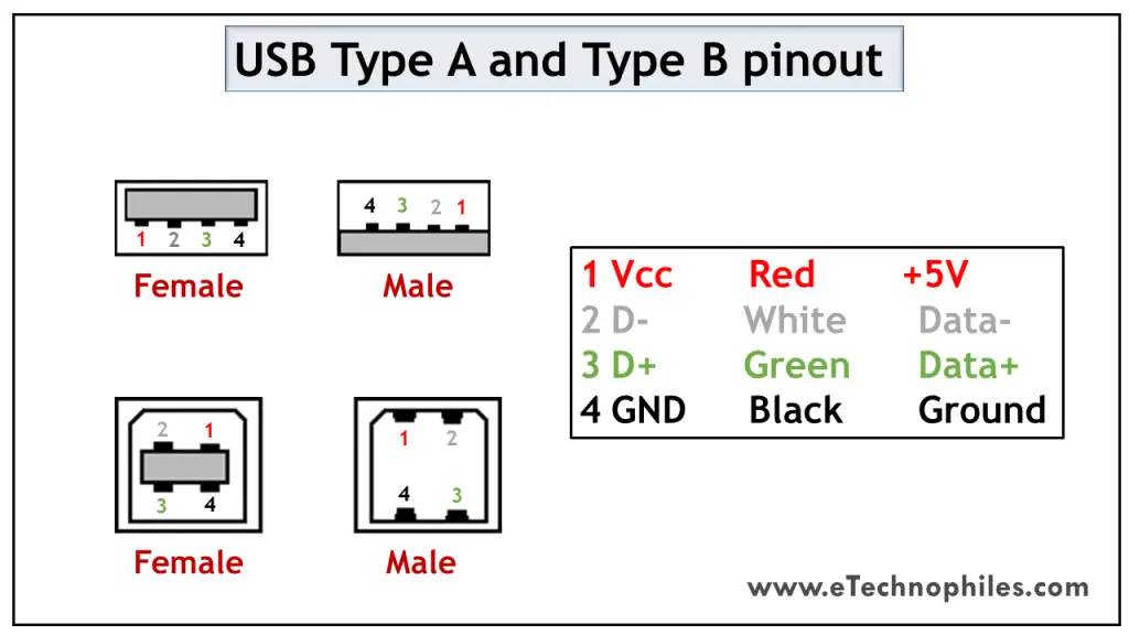
Both these USB types differ in purpose and shape, but their pin connections are the same. Pin 1 is dedicated to the supply and pin 4 is for ground connection. Even pin 2 and 3 take the data input in both these types.
The female port has the PINs in descending order, starting from the right-hand side, while the male connector has them in the reverse order. The table below shows the pinout of both USBs.
USB mini A and mini B
USB Mini was the first improvised version of the normal connectors. This version was launched for both Type A and Type B.
It’s a smaller version of Type A and B, which was extensively used with old mobile phones. The Mini B connector is more popular than the Mini A. The figure below shows the pinout of USB Mini B.
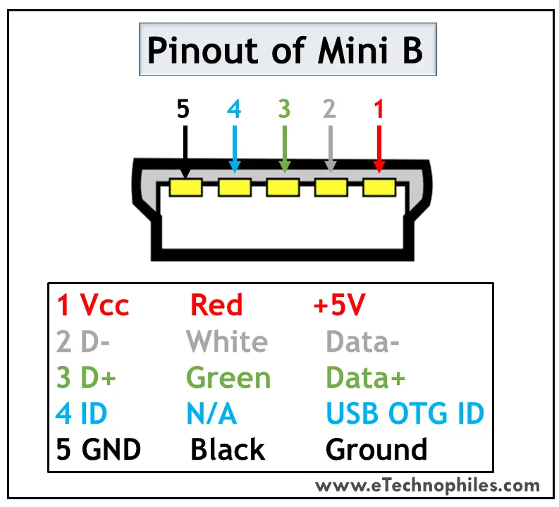
USB Mini B is thinner and more compact than Mini A. Hence it is used for PDAs, digital cameras, etc. Another significant development imposed on Type Mini is that it has an additional pin to support On-the-GO (OTG) connection. Thus it has 5 pins. The pin connections are given in the table below.
USB micro A and micro B
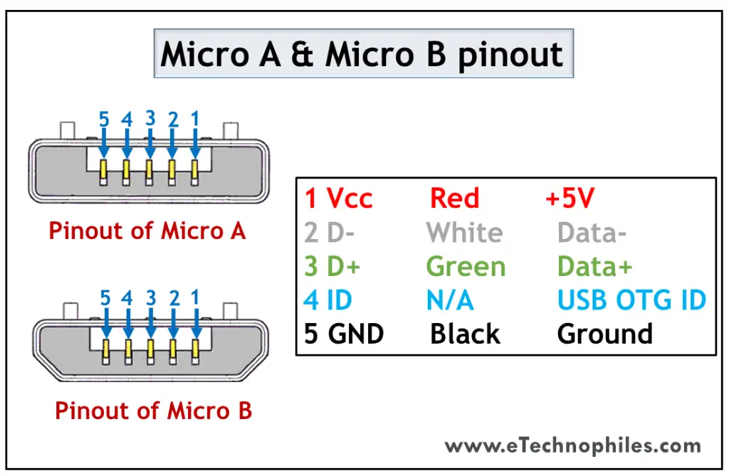
USB Micro is thinner and gives a higher data transfer speed than the USB Mini. It is often used for charging portable devices and comes in two shapes. Micro A is rectangular whereas Type Micro B has a camper shape.
The USB Micro also has 5 pins similar to that of the USB Mini, where the additional pin supports OTG connectivity. The table below shows the pinout of Micro-A and B.
USB standard 3
USB Standard 3 is widely known as the SuperSpeed Mode that brought a revolution in USB manufacturing. The models used in the third generation are highly advanced, offer faster data speed, have a compact design, and are easy to handle.
Features of USB standard 3
The standard 3 models are accepted globally due to the following benefits:
- It is capable of transferring data with a speed of 5Gbps and above.
- Since separate unidirectional paths are used to transmit and receive data, it has a larger bandwidth.
- With predefined power management states, it offers better power management.
- It allows the devices to notify about the data transfer, thereby improving the bus usage.
Standard 3 connectors come in the same physical configuration but with an additional 5 pins to handle these advancements. It includes additional ground and dedicated pins for transmission and reception which are called super-speed connections. ( learn more )
The pinout diagrams of the superspeed versions of different USB types are described in the following section.
USB type A 3.0 and type B 3.0
As discussed above, the normal Type A and Type B connectors have 4 pins. But the superspeed versions of Standard 3 have 9 pins which are visible in the figure below.
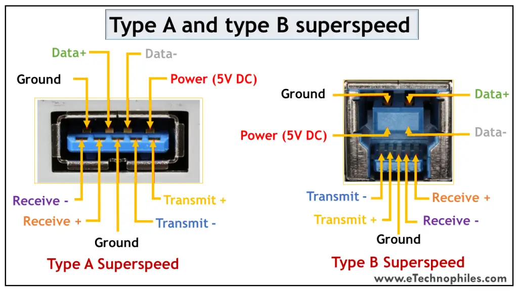
The table below shows the pinout of the superspeed versions.
Micro B 3.0
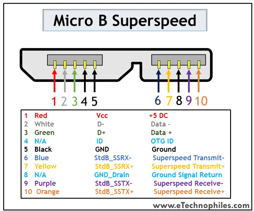
The superspeed version of Micro USB was introduced to Type B. Apart from the existing structure, the five additional pins are placed as an extension. Thus, it has a wider structure. The pinout of the Superspeed Micro B USB connector is given in the table below.
USB type c 3.0
Type C has been the game-changer among all the USB types. It supports data transmission as well as power delivery. Thus, it has become a universal connector for modern devices.

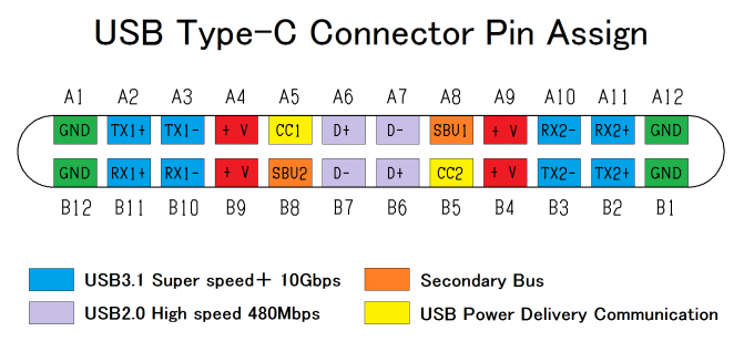
The major attraction of Type C USB is that it is flippable. The figure above shows the pin connections with their corresponding color. The pin connections at the top and bottom are similar, so we don’t have to bother to insert the connector in the correct direction.
It has an incredible data transfer speed of up to 5Gbps and is capable of replacing Ethernet ports to achieve higher data rates. The connection description is given in the table below.
About the Author
Blessy Simon
I’m an AI researcher who enjoys writing. Whether it’s crafting compelling blog posts or optimizing web content for search engines, I have a knack for tailoring my writing style to suit various niches and audiences. Read more
Blessy C Simon
2 thoughts on “10 USB Pinout Explained- USB A, B, C(Male and Female)”
Great knowledge about USB… Thank you
Glad to be of help.
Leave a Comment Cancel reply
PCB Manufacturing
Rigid-flex pcb.
- Heavy Copper PCB
- High Frequency PCB
- High Tg PCB
- Metal Core PCBs
- Aluminum PCBs
- Rogers Material
PCB Assembly
- Custom Cable Assembly
- Custom Wiring Harness
- Capabilities
- Pad Hole Ring Copper
- Pad Hole Ring Copper Specification
- Your Name *
- Phone Number *
- Tell us your needs (as specific as possible) *
- File (Gerber files and BOM need to be compressed into one ZIP file.)
Contact WellPCB Team
Usb pinout: the beginner’s guide.
Nowadays, it’s easy to complete projects that involve creating a physical connection between a host controller and several other bus-powered devices because of the USB interface.
USB stands for Universal Serial Bus and has since replaced its predecessors (FireWire, RS-232 serial, and even parallel) as the primary interface for connecting a host to a device.
Normally, the architecture of a USB system includes a host controller, USB ports, and a wide variety of devices. Also, there are cases where you can add additional USB network hubs to create a tree connection structure.
However, that’s just the surface of it all.
So, in this article, we’ll explain everything about the USB and give different USB examples for your circuits.
Let’s begin!

USB Flash drive
The USB has four shielded wires that work as pins. Two of these wires are for power supply, while the other two are for differential data signal pairs. Check out the table below for the full USB pinout.
How Does a USB Work?

plugging a USB pen drive on a laptop
Like all connectors, all types of USB connectors have male and female types, making sure you connect your devices in the right direction.
It’s essential to make correct USB connections to allow the system to follow the required USB protocol. So, to establish a connection, USB remote devices feature what we call an upstream connection. These remote devices use this upstream connection to connect to a host.
Now, the hosts also have downstream connections that allow them to connect to the remote devices.
Furthermore, you can’t use upstream and downstream connections interchangeably. This helps you avoid misconnections and makes sure you connect the USB cable only in the right direction.
It also helps you avoid several issues like illegal loopback connections and connecting a downstream port to another downstream port.
How it really Works
First, a USB device will show its maximum speed by using pull-up resistors to draw the “D+” and “D-” terminals to 3.3V. Now, the host or hub will also use these pull-up resistors to detect when you connect a compound device to its port. Thus, without a pull-up resistor, the USB won’t detect your connected device or if you have a broken device or broken connector .
So, when you plug in an external device for the first time, the host device scans it and loads the correct driver version required to run the device. To do this, the host uses a product ID/vendor ID (PID/VID)—which the connected hardware or device supplies. Once the host completes the loading of necessary device drivers, the hardware/device will be ready for use.
Note: USB host controllers have their specifications. We have the Universal Host Controller Interface (UHCI), which works for all USB types, the Open Host Controller Interface (OHCI), which works with USB 1.1, and the Enhanced Host Controller Interface (EHCI), which works with USB 2.0.
USB Connector Types
Originally, the USB cable could only be one of two types, and these two types included “Type A” and “Type B”. Afterward, we got the USB C type, which boasted a better data transfer speed with a more robust system.
Check out the table below for the full overview of the different USB types.

Type-A USB Connector Pinout
Type-A USB is the most popular type of USB connector. Plus, you can find them on host controllers, computers, flash drives, and several other items. Also, you can only make downstream connections with the Type-A USB as its sole use is for controllers and hubs.
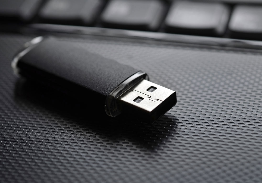
Flash Drive
Type-A USB connectors are bigger than other connectors and have flat and rectangular shapes. Plus, friction holds this connector in place, making it easy to connect and disconnect. However, using it in areas where your equipment might vibrate isn’t a great idea.
The Type-A USB has two versions: Male and female versions. The male version is the plug, while the female version is what we know as the socket or port.
Female connector versions are what we find on host controllers, while male connector versions are usually on devices like memory sticks, keyboards, mice, and other connections to storage devices.
Applications.
- Works in most personal computers.
- Also works in television and music systems.
- You can also find them on gaming consoles and almost all chargers for mobile portable devices.
Type-A USB Pinout
The older versions of the Type-A connector have four pins, while the newer versions have nine pins. Here’s a table showing all the pins of the Type-A connector.

Note: all generations of the Type-A USB connector have pins 1 to 4 while third-generation connectors have pins 5-9.
USB-B Pinout
The USB-B is the second connector type that mostly works for connecting peripherals like printers and scanners. Plus, their pinouts have a different arrangement.
It has an almost square shape with a slight bevel at the top end corners of the connector. Also, it uses friction to remain in place when connected.
The Type-B USB port is an upstream connector that you can only find on peripheral devices. Thus, most Type-B USB applications require A to B USB cables.
Here’s an interesting fact:
Type-B USB canceled out the chances of creating a connection between two host computers. Thus, helping to prevent damages.
This connector mainly works for peripherals like printers and scanners.
Like the Type-A USB, the older versions of Type-B have four pins, while the newer 3.0 versions have nine pins. Here’s a table showing all the pins:

Also, there is a second type of Type-B connector that has two extra pins:
Source: Wikimedia Commons
USB-C Connector
The USB Type-C is the USB specification that’s slowly replacing the USB-B. It’s a tiny 24-pin reversible plug that works for USB cabling and devices.
Type-C USBs can serve as connectors for both hosts and devices. Plus, you can find Type-C USBs in most recent mobile devices.
USB-C Connector Pinout
The Type-C USB has 24 pins which you can connect reversibly. Here’s a table showing the full list of pins:

Micro USB Pinout
A smaller connector became necessary as the technology required smaller USB sizes for many items like modern mobile phones and audio devices. Thus, the USB Microcontroller was born.
The micro USB has both Type-A and Type-B USB versions available, like the 1.0 micro-USB and 2.0 micro-USB. However, these versions are smaller, and you can use them for much thinner lines of equipment.
Additionally, the micro USB is the USB standard and offers better transfer rates from an external source.
Standard older micro USB connectors have five pins, while the less common 3.0 version has ten pins. Here’s a table showing the pins of the micro USB connector:

The fourth pin mode is what we call the USB on-the-go (OTG). It allows you to switch between the peripheral and host roles on your devices. It’s also what enables devices to decide which will act as a power source once connected. For instance, plugging an android phone into a laptop. The laptop will charge the phone if you have a charge-only cable, not the phone charging the laptop.
Wrapping Up
It’s worth mentioning that sometimes, it’s possible to use USB A to USB A cables to establish connections between a computer or USB device to another USB device with an A-style female port. So you can transfer data between both systems.
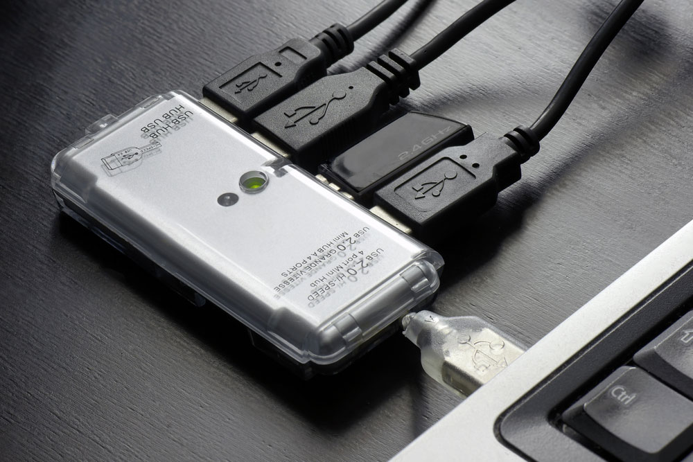
However, you shouldn’t use the type A to A cable connection to create connections between two computers or a USB hub and two computers. Why? Well, creating such a connection would mean the cable would receive equal amounts of voltage (5V) from both computers. Thus, connecting both power supplies and causing irreparable damage and other issues. Sometimes, it may even cause a fire hazard.
Well, that wraps up this article. Feel free to reach us if you have any questions, and we’ll be happy to help.

Cras quis nulla commodo
Circuit board fabrication and pcb assembly turnkey services.
To enhance your browsing experience, we use cookies. These cookies may contain your personal information. Please review our Privacy Policy for more information.By clicking "Agree," you acknowledge that you have read and agree to our Privacy Policy and the use of cookies. You can manage cookie preferences anytime in your browser settings.
Get 3 pieces of PCBs for Just $1! 🚀
- 👉 Choose between one or two-layer PCBs.
- 👉 Available in a variety of colors and thicknesses.
- 👉 Board dimensions must be within 100 x 100mm.
computer bus pin assignment
Usb-c (type-c) pinout.

- Ask a question
USB type-c details
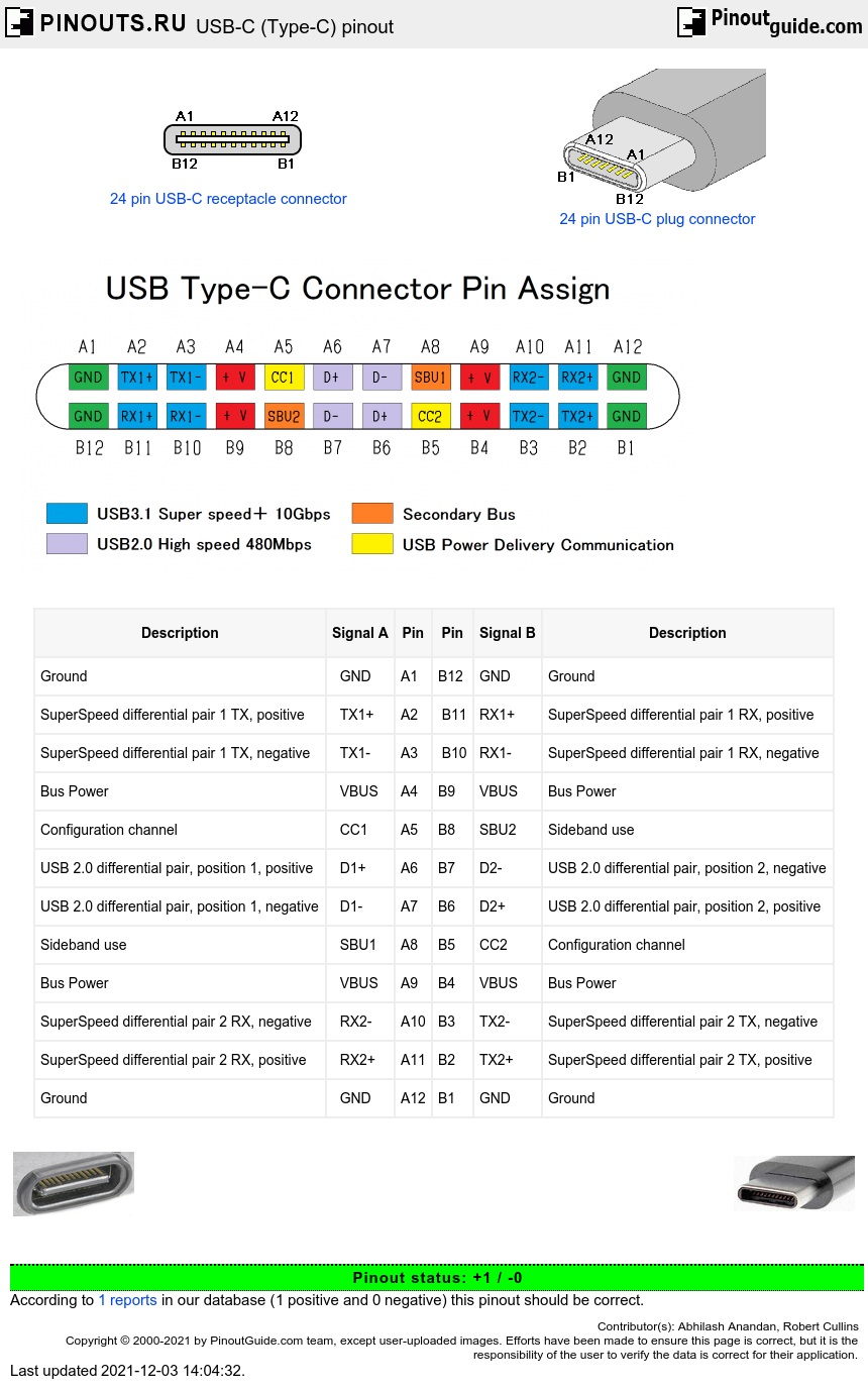
Developed at roughly the same time as the USB 3.1 specification, but distinct from it, the USB Type-C Specification 1.0 defines a new small reversible-plug connector for USB devices. The Type-C plug connects to both hosts and devices, replacing various Type-B and Type-A connectors and cables with a standard meant to be future-proof, similar to Apple Lightning and Thunderbolt . The 24-pin double-sided connector provides four power/ground pairs, two differential pairs for USB 2.0 data bus (though only one pair is implemented in a Type-C cable), four pairs for high-speed data bus, two sideband use pins, and two configuration pins for cable orientation detection, dedicated biphase mark code (BMC) configuration data channel, and VCONN +5 V power for active cables. Type-A and Type-B adaptors and cables will be required for older devices in order to plug into Type-C hosts; adaptors and cables with a Type-C receptacle are not allowed.
USB type-C pinout
Pins A2,A3,A10,A11,B2,B3,B10,B11 are not used with USB 2.0-only devices.
User uploaded image:
See also USB type C full-featured cable.

- USB-C (type-C) full-featured cable pinout
- USB-C (Type-C) to USB-A charge/data cable pinout
- USB-C to micro-USB 2.0 cable pinout
- USB-C to USB 3.2 cable pinout
- Automation & Control Gear
- Cables & Wires
- Enclosures & Server Racks
- Fuses & Circuit Breakers
- HVAC, Fans & Thermal Management
- Relays & Signal Conditioning
- Batteries & Chargers
- Displays & Optoelectronics
- ESD Control, Cleanroom & PCB Prototyping
- Passive Components
- Power Supplies & Transformers
- Raspberry Pi, Arduino, ROCK & Development Tools
- Semiconductors
- Access, Storage & Material Handling
- Adhesives, Sealants & Tapes
- Bearings & Seals
- Engineering Materials & Industrial Hardware
- Fasteners & Fixings
- Mechanical Power Transmission
- Plumbing & Pipeline
- Pneumatics & Hydraulics
- Power Tools, Soldering & Welding
- Computing & Peripherals
- Facilities Cleaning & Maintenance
- Office Supplies
- Personal Protective Equipment & Workwear
- Security & Ironmongery
- Site Safety
- Test & Measurement
- Published 30 Jan 2023
- Last Modified 29 Aug 2023
A Complete Guide to USB Connectors
Our USB connectors guide explains their purpose, uses, and the different types and standards available.

Reviewed by Jay Proctor, Technical Support Team Leader (November 2021)
This handy guide to USB connectors will tell you all you need to know about choosing and buying them online. By the end of the guide, you will be familiar with exactly what USB connectors are, and which types are best in which roles.
You will also know the purpose of different sorts of connector, as well as how to identify and purchase the right type of connector online. We will provide clear answers to some common FAQs about the various types of USB interface jacks and ports in widespread use.
What is a USB Connector?

A USB connector is the socket, port, or jack into which the plug end of a USB cable or USB-powered device is inserted. USB connectors are typically female, while the USB plug on the cable is male.
Rectangular, slot-shaped USB type-A connectors are most common and can be found on computers, personal electronics, and peripherals. This includes keyboards and mice, mobile phones and chargers, memory sticks (flash drives), and other USB accessories .
What Do USB Connectors Do?
Female USB connectors allow the male part of a USB cable or plug to be inserted into any compatible device. Once coupled in this way, the two devices can share both power and data over their common USB connection.
USB stands for Universal Serial Bus, a common standard launched in 1996. Before this, there was a much wider variety of different connectors commonly used for linking PCs and compatible hardware. Examples you might be familiar with include multiple versions of serial ports, D-Sub , and parallel ports.
The body responsible for developing, maintaining, and updating the USB standard is called the USB Implementers Forum, or USB-IF. To date, there have been four main generations of USB released: USB 1.x (which had various subcategories), USB 2.0, USB 3.x (again, with subcategories), and USB 4. You will often see these referred to as USB gen 1, USB gen 3, and so on.
Between these four generations and the various shapes and types of USB connector available, we now have quite a wide range of USB port and socket standards available to choose from. The main difference between older and newer USB generations is the speed at which they can transfer data between one device and another. This is shown in the chart below:
Where Can They Be Found?
USB ports and plugs were developed to simplify the process of connecting multiple different USB devices and peripherals to computers. While many older port types are still in widespread use today (especially for legacy hardware), fewer new peripherals are being manufactured that rely on them.
In their place, USB interface connectors have quickly become a near-ubiquitous feature. Today, you will find USB connections in almost all types of electronics and communications hardware, from laptops and mobile phones to printers , microphones and headphones , and even cars.
In short, almost every device that includes a PCB (printed circuit board) will likely have at least one type of USB port on it somewhere. PCB USB connectors and related components are cheap to buy, and easy to mount in a variety of ways including panel, surface, through-hole, and cable mount.
It is also worth noting that many device types also now support a newer standard called USB On-The-Go (USB OTG), which enables certain products to switch between host and device roles. A common example would be a mobile phone, which can act as both a mass storage device itself and a USB reader for importing data from external peripherals.
USB Connector Types
There are currently several USB types in widespread use. However, USB connector types should not be confused with USB generations. Generation refers to the age and speed of the connector, while the type is defined by the shape of the port and the corresponding cables or plugs that can be used with it.
In the sections below, we will cover each of the main USB types (Type-A, Type-B etc), and then discuss the differences between connectors for older and newer USB generations (USB 2.0, 3.0 etc).
A Type Connectors
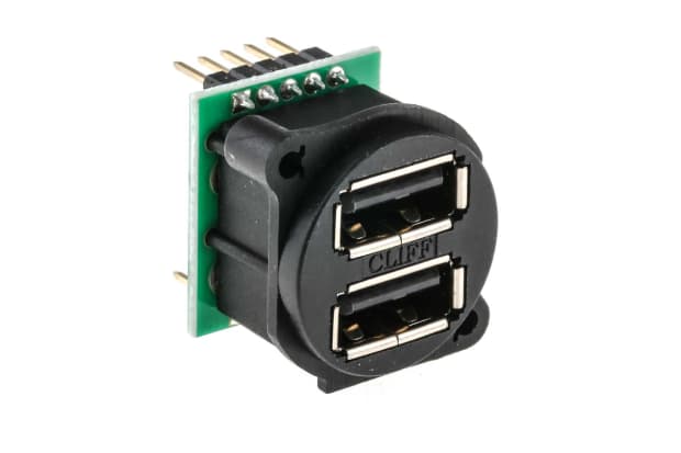
The most popular and common USB port type today is probably the USB Type-A, also known as Standard-A. USB A connections will be very familiar to most PC or laptop users as a rectangular slot of about 14mm wide by 6mm high.
Most computers will have several of these receptacles on the side, back or front of the case, allowing multiple external devices and peripherals to be attached via a cable. The USB Type-A connector is fully backwards compatible with all generations of USB Type-A plug, from 1.0 through to 3.2. The upcoming USB4 standard, officially announced in 2019, relies on a differently shaped USB Type-C port.
Type-A USB plugs are held in the connectors by friction, with flat contacts at the terminals that slide together when a male plug is inserted into a female jack. They can only be inserted one way around, as the terminal block inside a Type-A connector is slightly off-centre.
They are mainly intended for use as a downstream USB connection to smaller devices. This allows peripherals and accessories requiring data or power delivery (up to 5V) to be plugged into a host controller or hub device that supplies it.
B Type Connectors
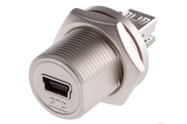
USB Type-B ports are roughly square, rather than being a narrow slot like Type-A. The upper corners of the square USB Type-B connector (and its corresponding USB-B plugs) are slightly angled. This means the receptacle will only accept a connection when the male part is orientated the right way up.
USB Type-B is primarily intended for use as an upstream connection. This means it is more often found on peripheral devices designed to connect directly to the host device, to send data to it. A typical example of somewhere you will often see a Type-B USB port is on an external hard drive dock (i.e. a powered hard drive enclosure ).
C Type Connectors
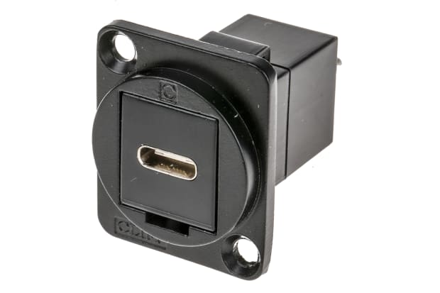
USB Type-C connectors are one of the newest and fastest standards of USB type. Increasing numbers of the latest cutting-edge hardware devices are now being released with one or more USB Type-C ports already built in.
Unlike Type-A and Type-B connectors, female USB-C ports can accept a male USB-C plug inserted either way up, as the terminals at both port and plug are completely symmetrical. Type-C USB connectors can be used with adapters that allow the connection of various other USB types, and they are capable of transferring power and data to/from all previous generations of USB devices.
USB Type-C jacks are much smaller than Type-A or Type-B variants, but they can send data far more quickly than older models. With an upper-end throughput of up to 10 Gbps, USB-C cables and ports also support increased power delivery of up to 20V and 100W. This makes them ideal for rapid data offloading, as well as for fast charging of high-end modern peripherals via cable.
Micro USB B Connectors
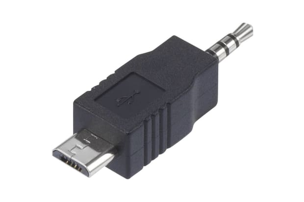
A Micro USB or Micro-B connector (more properly referred to as a Micro-USB B, per official USB-IF recognition) is a smaller sized version of the USB Mini-b. Both are physically reduced models of Micro USB connector.
They are commonly found on rechargeable technologies and smaller peripherals. Micro-USB B, being the smaller of the two, is often seen on newer devices, while the slightly bigger USB Mini-b is now less widely used.
Both mini USB and Micro USB are now technically deprecated. The mini doesn’t support USB gen 3.0 (2011) or later, while the Micro retained support for USB gen 3.1 (2014), but not 3.2 (2017). However, you will still find these small connectors on devices that do not yet come with a Type-C port as standard.
Mini USB Connector Pinouts
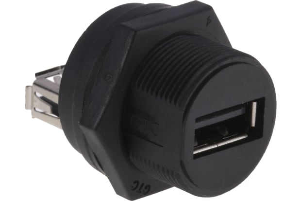
Mini USB pinout is something you need to be aware of when plugging into either of these smaller USB ports. Whereas the USB connector pinout on other models will be the same for all connectors of that type, there exists both a 5-pin and a 4-pin version of USB Mini-b sockets.
Only the USB Mini-b 5-pin connector is officially recognised by the USB-IF, and unless otherwise specified, all USB Mini-b jacks are assumed to be 5-pin. Even so, a more compact 4-pin model is still used by several manufacturers, and by makers of some leading brand digital cameras.
It is relatively rare to find a 4-pin Mini-b connection in other device types. However, it does not belong to any single manufacturer. You can recognise the 4-pin USB connector quite easily, as it is roughly square, and closely resembles a very small USB Type-B port.

USB 2.0 Connectors
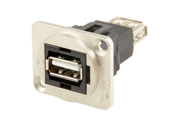
USB 2.0 connectors refer to the generation, not the USB type. Most USB types will be compatible with all generations of USB standard, but newer gen ports will be faster.
USB 2.0 was a generational improvement that launched in 2001 and was later revised. It remained the latest and fastest USB standard available until 2011 when USB 3.0 arrived.
Data transfer speeds available via USB 2.0 are 1.5 Mbit/s (Low Speed), 12 Mbit/s (Full Speed), and 480 Mbit/s (High Speed). The maximum speeds you can achieve will depend largely on the capabilities of the devices you are connecting and the quality of the cable, plug and connector.
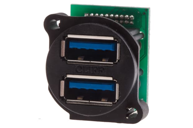
USB 3.0 Connectors
USB 3.0 launched in 2011, superseding the previous USB 2.0 standard and offering speeds of up to 5 Gbit/s (SuperSpeed). It has since been updated twice, with USB 3.1 (2014) offering transfer rates of up to 10 Gbit/s, and USB 3.2 (2017) up to 20 Gbit/s (both designated as SuperSpeed+).
Available USB 3 connector types include 3.x A-Type, 3.x B-Type, and USB 3.x Micro B. There are no USB 3.0 Mini-b connectors, as the Mini-b standard only supports up to USB gen 2 signals.
It was announced in 2019 that USB 3 would not remain the latest standard for much longer, as products supporting USB 4 (officially written as USB4) began to launch in mid-2020. USB4 is based on the Thunderbolt 3 protocol and supports tunnelling of DisplayPort and PCI Express, as well as a throughput of 20-40 Gbps.
Non-Standard USB Connectors
A non-standard USB connector would broadly be any USB-compatible port, socket or connection adapter that falls outside the commonly used mainstream types listed above. This could include products such as:
- Micro USB-A - mostly found on newer devices that lack a faster Type-C port
- Mini A/B - a versatile connector that can accept either mini A-type or mini B-type plugs and cables
- Micro AB - a smaller version of the above type, designed solely for use in USB-on-the-go devices
- USB converters and adapters - including A to A, B to B, A to B and B to A
Industrial USB Connectors
An industrial connector is typically one that is designed for extremely hard-wearing use in a more challenging environment. This might include versions designed with:
- IP ratings for resistance to dirt and moisture ingress
- Fully waterproof durable thermoplastic housings
- High-retention or latching mechanisms to prevent accidental disconnection of friction-based USB port types due to snagging, vibration, or sudden movement
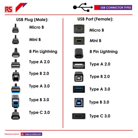
What is the Difference Between Male and Female Connectors?
The difference between male and female connectors - the two connector genders - is that one gets plugged in, while the other gets plugged into.
A female USB connector refers to the port, also known as a slot, receptacle, or socket. This is what you will typically find on host devices or hubs, allowing external USB devices and peripherals to be plugged in.
The male USB connector - typically called the plug - is almost always found on the end of a cable, or sometimes physically attached to smaller accessories such as USB memory sticks. This inserts into the female port, usually located in the casing of a larger device.
Male and female connectors can be found for all types of Universal Serial Bus jacks - Micro USB-B male connector, USB-A female connector, and so on. This is because you will always need two components of opposite genders to couple together to form the connection, regardless of what type you are using.
You can also buy various gendered adapters and converters for all types and generations of USB connector. These include male-to-male, female-to-female, male-to-female, and female-to-male USB ports.
Related Guides
We're sorry but your browser is not supported
To ensure the best online experience possible, please upgrade your browser or contact us.
Tel:1-855-326-4757
Email: [email protected]
Subscribe Today & Save 10% on Your Next Order
- Parametric Search
Product Categories
Circuit Protection
Computers and peripherals, electromechanical, kits and tools, led lighting, optoelectronics and displays, semiconductors, test and measurement, thermal management, tools and supplies, wire and cables, ip&e components.
- Electrical Distribution and Protection
- ESD Protection Diodes
- Overcurrent Protection
- Surge protection Modules
- Computer Products
- Kits & Tools
- Connector Accessories
- I/O Connectors
- Connector Other
- Wire and PCB Connector
- Audio Components
- Electromechanical Switches
- Flow & Level
- Mechanical Power Transmission
- Motion Control and Fluid Power
- Capacitive Encoders (74)
- Magnetic Encoders (35)
- Mechanical Encoders (979)
- Optical Encoders (672)
- Clock and Timing
- Data Conversion Development Boards and Kits
- Development Kits and Tools
- Development Systems
- Embedded System Development Boards and Kits
- Flash Cards
- Power Management Development Boards and Kits
- Programmable Logic Development Boards and Kits
- RF and Microwave Development Boards and Kits
- LED Accessories
- LED Displays
- LED Indication
- LED Lighting
- Lighting Fixtures
- Optoelectronics
- EMI/RFI Suppression
- Oscillators & Crystals
- Power Line Filters
- Power Management
- Power Supplies
- Attenuators
- Communication
- Controllers
- Data Acquisition
- Diodes, Transistors and Thyristors
- Electronic Switches
- Microcontrollers and Processors
- Networks and Interfaces
- Programmable Devices
- RF and Microwave
- Standard and Specialty Logic
- Transceivers
- Accelerometers (865)
- Air Quality Sensors (333)
- Ambient Light Sensors (349)
- Angular and Linear Position Sensors (2238)
- Board Mount Pressure Sensors (4536)
- Color Sensors (83)
- Current Sensors (1334)
- Fan Controllers (377)
- Flow Sensors (216)
- Force Sensors and Load Cells (286)
- Gyroscopes (194)
- Hall Effect Sensors (3259)
- Image Sensors (1649)
- Industrial Pressure Sensors (2569)
- Level Sensors
- Magnetoresistive Sensors (234)
- Photoelectric Sensors (619)
- PIR Sensors (600)
- Proximity Sensors (1696)
- Safety Light Curtains (42)
- Sensor Accessories (1925)
- Sensor and Gateway Kits (30)
- Sensor Development Boards and Kits (3359)
- Sensor Actuator Boxes ()
- Smoke Detectors (109)
- Specialized Sensors (1566)
- Strain Gages (5)
- Temperature and Humidity Sensors (3978)
- Thermistors (9892)
- Thermostats (1482)
- Accessories
- Electrical and Electronic Test Equipment
- Oscilloscopes, Generators and Analyzers
- Fasteners and Hardware
- Materials, Chemicals and Adhesives
- Pipe, Tubing, Hose and Accessories
- Cable Assemblies
- Cable Management Accessories
- Contact Blocks (411)
- Dimmers (20)
- Switch Accessories (8583)
- Switch Detector (561)
- Switch DIP (4747)
- Switch Emergency Stop (213)
- Foot Switches (34)
- Switch Indicators (660)
- Switch Key (850)
- Switch KeyLock (1021)
- Switch Limit (2215)
- Switch Other (468)
- Switch Piezo (102)
- Push Button Switches (8841)
- Switch Reed (629)
- Rocker Switches (4673)
- Rotary Switch (4024)
- Switch Safety Interlock (543)
- Switch Selector (466)
- Switch Slide (2503)
- Snap Action Switch (7933)
- Tactile Switch (5443)
- Switch Thumb-Pushwheel (310)
- Switch Toggle (9314)
Manufacturers Our Featured Partners
19,065 products.
Manufacturers
- Reference Designs
- Articles - Videos - Events
Sorry, there was an error loading the page.
Please refresh the browser and try again. If the problem persists please contact us
Micro USB Pinout Explained

USB cables come with one of five different basic types of USB connector: A, B, mini B, micro B, and C. The micro connector comes standard on most non-Apple mobile phones and many other portables, though USB-C connectors are slowly replacing them in the newest generation of devices.
The USB Standard
The standard micro connector is available only up to the second-generation USB standard, though a less common and much wider 3.0 version exists. The 3.0 version offers:
- Better transfer rates than 2.0, but it’s less practical than the smaller and faster USB-C connector.
- Receptacles that can accept older generation cables, but older receptacles cannot accept 3.0 cables.
The standard micro connector has five pins in its older generations and ten pins in the less common 3.0 generation:

What is USB OTG?
The fourth pin (mode detect) is also commonly referred to as USB “On-the-Go” or simply “OTG.” This pin allows devices to switch between host and peripheral roles. In a smartphone, for instance, the USB connection might allow the phone to perform as a mass storage device when connected to a computer, but as a host to read data from removable storage. This OTG pin is also what allows devices to “decide” which will draw power from the other – typically the host will supply power to the peripheral, though in some cases the roles may be re-negotiated.
Micro USB Pinout Diagrams
Looking at the micro connector on a cable, all generations have pins numbered 1-4, ascending, from left to right on the main trapezoid. Third generation connectors have pins 6-10, ascending, from left to right, on the added side rectangle. You’ll find shielded wires on these connectors, and the data wires (positive and negative) are twisted pairs requiring no termination.

Fig 1: USB A and USB Micro B pinout

Fig 2: USB 3.0 Micro B pinout
Article tags
Related news articles.
- Arduino Corporation
How to Use Raspberry Pi With Arduino Via USB Serial
- Diodes Incorporated
Integrated Solutions to USB Type-C Port Implementation Challenges
- Silicon Motion Technology
- Application Processor and SoC
Silicon Motion's Graphics Display SoCs: Enhancing the User Experience in USB Docking Stations
Usb connector types: mini usb connectors & pinouts, what is a usb c connector usb type c connector standard explained, type b usb connectors & pinouts, modern usb advancements: micro b, c & lightning, type-c usb port mainstream device that triggered exploding demand, important decisions when selecting a fan for forced air cooling, latest news, arrow & infineon 240w usb pd reference design board.
- Infineon Solutions
Fast EV Charging trends and system solutions
- Analog Devices
- ADI Industrial
- Motor control
Saving the Planet One Motor at a Time
In this article from Analog Devices, explore how the process of making electric motors more efficient can aid in reducing the emissions that contribute to climate change.
Arrow Newsletters: Subscribe Now and Save 10%
Connect with electronic components.
Contact and Support
- Contact Arrow
- Find an Arrow Office
- Shipping Information
- Arrow Vendor Registration
- Return Policy
- Accessibility
Programs and Partners
- ArrowSphere
- Electronic Components API
Featured Products
- Internet of Things
- All Products
- LEDs and LED Lighting
- Wire and Cable
- All Categories
- Infineon Technologies AG
- Silicon Labs
- STMicroelectronics
- TE Connectivity
Verticals & Trends
- Energy and Power
- Security Solutions
- Electrification of Everything
- Autonomous Machines
- Smart Everything
- Energy Management
We've updated our privacy policy. Please take a moment to review these changes. By clicking I Agree to Arrow Electronics Terms Of Use and have read and understand the Privacy Policy and Cookie Policy .
- Accept Terms
Our website places cookies on your device to improve your experience and to improve our site. Read more about the cookies we use and how to disable them here . Cookies and tracking technologies may be used for marketing purposes. By clicking “Accept”, you are consenting to placement of cookies on your device and to our use of tracking technologies. Click “Read More” below for more information and instructions on how to disable cookies and tracking technologies. While acceptance of cookies and tracking technologies is voluntary, disabling them may result in the website not working properly, and certain advertisements may be less relevant to you. We respect your privacy. Read our privacy policy here
Continue to site >>>

USB TYPE-C Connector
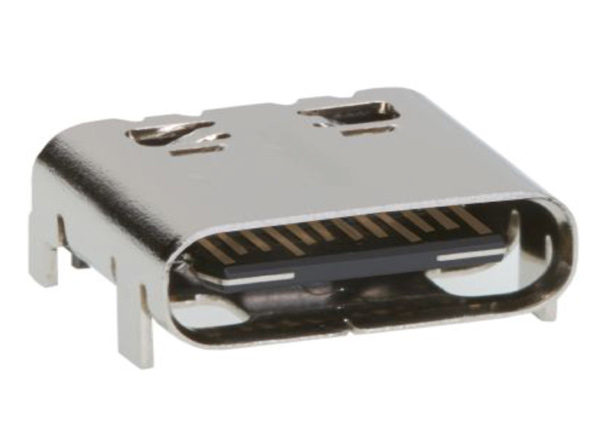
[Click the image to enlarge it]
USB TYPE-C is a new port designed for high speed data exchange and high power deliver capability. The first thing to realize is that USB TYPE-C is not a new USB standard like USB1.0, USB2.0 , USB3.0, and USB3.1. Those are protocols defining speed and other features, whereas USB TYPE-C is all about physical connection.
USB TYPE-C specification was published by USB Implementers Forum (USB-IF) and was finalized in August 2014. It is a 24 pin USB connector , which is distinguished by its two-fold rotationally-symmetrical connector as shown in above picture.
USB -C connector is designed for replacing USB-A and USB-B connectors. It is also designed for supporting USB3.1 standard fully. It is now poised to become the universal port.
USB Type-C Pin Configuration
As mentioned earlier USB-C is a 24 pin connector and we will describe the each pin below.
The awkward fumble over connecting a pen drive to USB port is finally over with USB-C. The orientation needs to be correct for connecting a pen drive to a USB-A port where as in USB-C port it is not necessary. You can connect devices irrespective of orientation to the USB-C and the port will auto detect the device. So USB TYPE-C is reversible port. Also USB-C is to replace both USB-A and USB-B, so connectivity at both PC and SMART PHONE remains the same. We can connect any end of the cable to PC or SMART PHONE. The issue of connecting correct end of the cable to the PC or MOBILE will be solved permanently with USB-C port.
Features and Electrical Characteristics
- High data transfer speeds up to 10Gb/s
- Up to 5Amp current handling capacity
- Reversible plug orientation and cable direction
- Small size similar to USB2.0 micro-B
- Designed to establish future USB performance needs
- USB-C can replace video ports like VGA and HDMI to provide high quality video output. It can deliver Ultra HD (4K) video for good gaming and movie experience
- USB-C can also replace audio output or 3.5mm jack to provide high quality audio or music in your smart phone or tablet
- USB-C can also replace Ethernet port to provide high speed internet up to 1000Mb/s
- USB-C can also replace SD card port, power port and all other to truly become universal port.
- Operating temperature: -30ºC to +85ºC
Note: Complete technical details can be found in the USB Type-C Connector Datasheet , linked at the bottom of this page.
Brief About USB TYPE-C
USB-C has become the new trend after its introduction. All the latest Laptops, Notebooks, Smart phones, Peripherals, Tablets and Memory devices are tend to be installed with USB-C. We can see new MACBOOK has only a single USB-C port to replace all other ports. In MACBOOK all the functions are done by that single port. Also GOOGLE CHROME BOOK PIXEL and new smart phones are having USB-C to promote for its application in all other areas.
How to use the USB TYPE-C
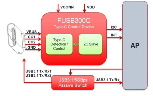
As mentioned earlier the features provided by USB-C are many. With so many features in a single port comes with complex management. So we need a port controller for using USB-C port. There are different controllers available in the market like TPS65982, FUSB300C and UPD360. We have to choose the appropriate controller depending on the requirement. A typical internal circuitry for USB-C is given below.
Applications
- Laptops and Notebook
- Personal Computers
- Tablets and Music players
- Printers and Scanners
- Digital cameras
- LCD and LED monitors
- Set top boxes
- Factory automation
- Medical devices
- Data centers
- Power packs and chargers
- Industrial machinery
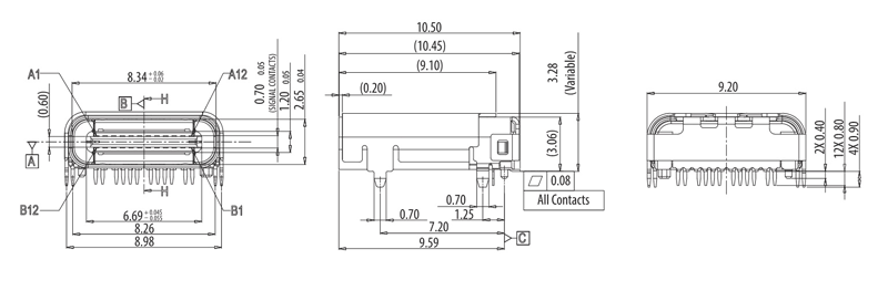
2-D Model and Dimensions
All measurements are in millimeter
Related Post
Join 20k+subscribers.
We will never spam you.
Be a part of our ever growing community.

Capable of supporting up to 32 GT/s without altering design

3M™ TwinAx High Speed Cable Solutions: Thin, low profile cable with extremely tight bend radii

Advantech's WISE-750 vibration PHM gateway is developed to perform predictive maintenance.

Industrial plating option with enhanced durability for a variety of harsh environments

ECS-3215MV-327KE compact 32.768 kHz MultiVolt oscillators offers low 1.3 µA current consumption.
Hammond’s modern 1556 series enclosures are designed for circuit boards and IoT equipment

Optimized with highly sensitive cap touch sensors, extensive peripheral circuits and 125℃ operation

KEMET's automotive PCB-mount relays unique structure offers high performance and productivity
USB C Pinout – All USB 2.0-3.0 Type Pin Diagram
Blog , Circuits
For those with a passion for technology and having an interest in the detail workings of modern connectivity, understanding the USB-C pinout is like uncovering the blueprint behind this remarkable connector. In this article, we will explore the vast and interesting detail of USB-C, which is serving to the modern electronics and to the tech enthusiasts, hobbyists, and engineers. Unraveling the complexities in simple words, and exploring the boundless possibilities it enables.
The USB C connector nowadays is most commonly used for charging mobile phones and various other portable devices like Bluetooth headset, Bluetooth speaker, Mini drones, Power Banks and various other tech gadgets not limited to emergency lights, LED decorative lamps.
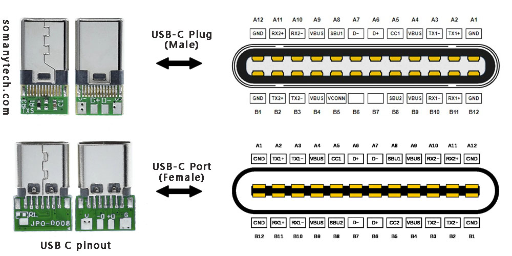
To the left in the above image are USB connectors with board as a USB 2.0 mode utilization, (D+, D-, VBUS, GND). Note that the USB 3.0 are fully functional cables connections are implemented with 8 or 10 connecting wires/bus.
The 24-pin double-sided connector offers a USB-C port that measures 8.4 x 2.6 x 6.65 mm. The 8.4 millimeters (~0.33 inches) is its width, the 2.6 millimeters (~0.10 inches) is its height, and the depth of 6.65 millimeters (~0.262 inches). The dimensions are for the internal side of a receptacle and outer side of a plug. And for more details refer to the datasheet provided by the manufacturer. These connectors come in two forms: a male/ plug and a female/ receptacle. (see image above)
The Plugs are commonly found on cables and adapters, providing the means to connect devices. On the other hand, receptacles can be found on devices and adapters, providing a socket for the plug to be inserted into and for establishing connections.
Simplified USB C pinout with their functions are as follows:
The USB C pinout table, offering resources on the intricate details of USB-C connectors. By reading the table, you could understand various pins and their vital functions, enabling a comprehensive understanding of how USB-C devices and cables work together in conjunction.
With careful attention to detail, the table unveils an array of essential pins such as VBUS, GND, CC1, CC2, D+, D- and so on. Each pin have a distinct purpose, from power supply and communication channels to data transmission and more.
It’s a complex network of connectivity enclosing power delivery, audio, video, and alternate modes. As you explore USB protocols, you’ll gain a profound insight of the complex signals and connections within the USB-C ecosystem.
Below is an image showing USB type C 3.0 modules for high speed data communication:
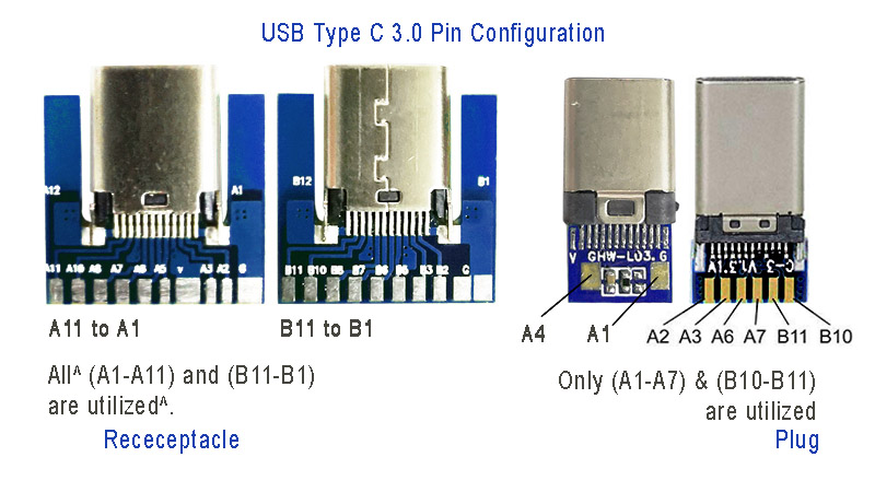
Power: The A4, B4 and A9, B9 are connected to supply voltage. Also A1, B1 and A12, B12 are grounded. Thus, number of pins and wires to GND and VCC are reduced to 2 only.
SBU1, SUB2: These pins are called secondary bus. The A8, B8 are for side-band and are not utilized in USB communication and are reserved for future use. And therefore, the functional pins on each side remains to 9 each.
CC1 or CC2: These pins are used for Pin configuration detection, CC is used for USB-PD, i.e. USB power delivery communication to determine current control to the devices, for example charging current. Generally, CC is connected in series with a Resistor = 56k at port end. Thus, the total wires in the cable is found to be minimum 8 in numbers for functional high-speed USB C 3.0/ 3.1 type.
Also check micro USB pinout and how it is different from type C connectors .
Click here for helpful -> “ wiring diagram for USB 3.0″ high speed data support and device charging .
Below is an image showing USB type C 2.0 modules for older data transfer and charging:
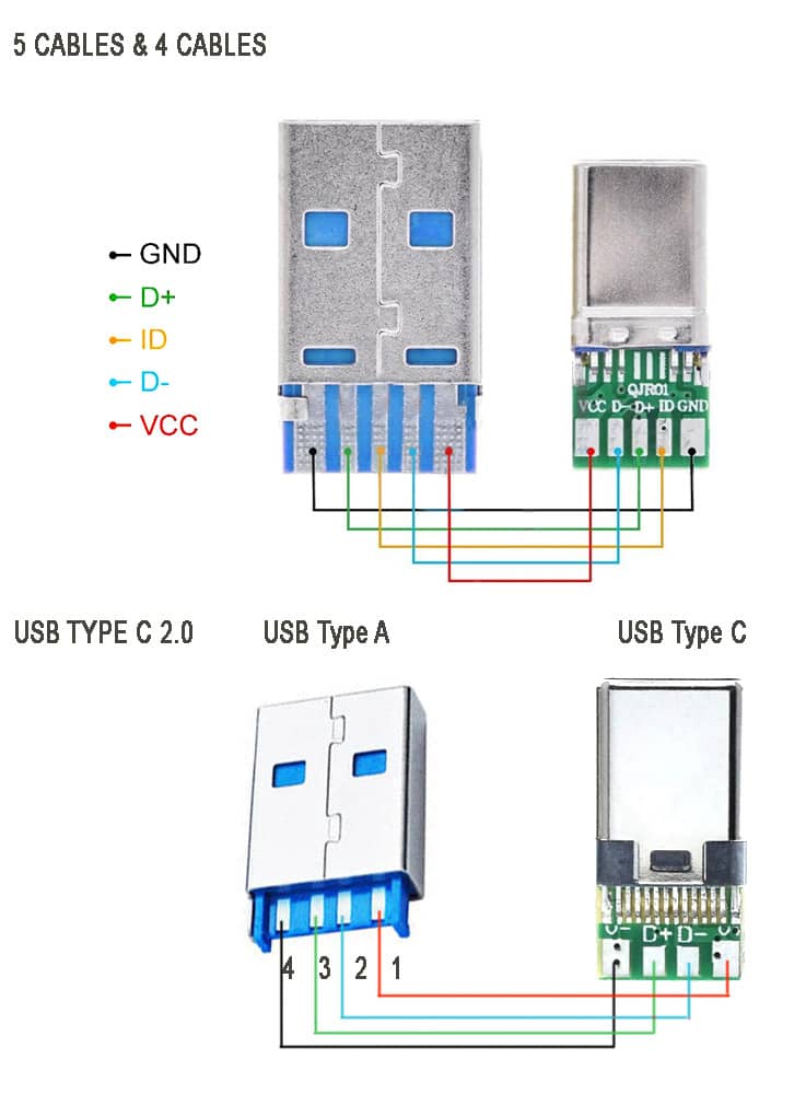
The above image showing the schematic diagram USB type C 2.0 older standard version of mobile phone charging and data transfer cable . Note that there are two types available, one with ID pin and without ID pin. ID pin is sometimes connected to the ground or connected in series with some resistor.
These cable supports both power and data transfer, there are also power only charging cables that support only charging. Meaning, you cannot use them for tasks such as syncing devices, transferring files, or connecting peripherals. They are solely intended for charging purposes. They come with only two connecting wires inside, and they are thicker wires to offer lower resistance to the current flowing though them.
These are made to target devices like neckband/ earphone charging, for charging mobile-phones, USB powered LED lamps and other gadgets that have nothing to do with the data transfer. They are less expensive than the one with data sync capability.
Related Posts

Blog , Component ID
8205A IC Datasheet PDF, Pin-out & Equivalent Mosfet IC
Here is the detailed information on the features, applications, uses, and specifications of this popular and most commonly found dual Mosfet 8205A IC with datasheet. If you are looking for a high current transistor to use in battery protection, load switching, or power management PCB circuit, this Dual MOSFET is designed in a way to […]

Top 11 Best Scientific Calculator App for Android – 2024
Utilize to the fullest the Android phone with the Best Scientific Calculator App, this app is very useful for Students, Engineers, or anyone requiring to calculate large complex scientific calculations which are more time consuming and not necessary to do manually. This powerful tool combines advanced mathematical functions with a user-friendly interface, making it the […]

Circuits , Component ID
IRF540, Datasheet PDF, Specification, Circuits, Pinout, Equivalent, Alternatives
For the high-current switching application, the IRF540 MOSFET is one of the popular choice. The IRF540 stands out for its fast switching, rugged device design, low on resistance and cost-effectiveness. In this article, we have discussed IRF540, check its pinout, equivalent, practical applications, distinctive features, as well as instruction on when and where to employ […]

IRF4905, Datasheet PDF, Specification, Pinout, Circuits, Alternatives
In need of high-current switching application, the IRF4905 MOSFET is one of the preferred choice. The IRF4905 stands out for its reliability and efficiency, making it the preferred selection for applications requiring rapid switching speeds and the power control system. In this article, we have discussed IRF4905, check its pinout, equivalent, practical applications, distinctive features, […]

Privacy policy
ASUS S300N Specification (claimed by the manufacturer)
Package content:, first impressions, operation, ergonomics, warranty and service, conclusions.
Write a comment below. No registration needed!
Buy computer microphones at tmart.com with free shipping
Platform · Video · Multimedia · Mobile · Other || About us & Privacy policy · Twitter · Facebook
Copyright © Byrds Research & Publishing, Ltd., 1997–2011. All rights reserved.

IMAGES
VIDEO
COMMENTS
USB type A and type B pinout (male and female) USB Type-A is used to make a connection with a PC while Type B is used to connect smaller peripherals. In other words, Type A is a downstream connector, while Type B is an upstream connector. The USB type A is rectangular, while type B has a square-like shape. Both of them have 4 pins.
USB pinouts diagram is a graphical representation of the different pins and their functions in a USB connector. It is essential to understand the pinouts diagram when working with USB cables or devices, as it helps in correctly connecting the wires and ensuring proper functionality. 1. VCC (Power): One of the most important pins in USB pinouts ...
Nowdays there are 7 USB connectors known: Standard-A, Standard-B, Mini-A, Mini-B , Micro-A, Micro-AB, Micro-B, Type-C. Mini-USB pinout and Micro-USB pinout are slightly different: standard USB uses 4 pins while Mini-USB and Micro-USB uses 5 pins in connector. The additional pin is used as an attached device presence indicator.
The USB cable schematic diagram typically includes information about the pin assignments and functions of the four standard USB cable wires: VCC (power), D+ (data), D- (data), and GND (ground). These wires carry power and data signals between USB devices, enabling communication and charging. The schematic diagram also shows the wiring ...
USB 3.0 details. USB 3.0 is the third major version of the Universal Serial Bus (USB) standard for interfacing computers and electronic devices. USB 3.0 combines USB 2.0 bus and new SuperSpeed bus with transfer rate up to 5.0 Gbit/s, which is about ten times faster than the USB 2.0 standard. USB 3.0 connectors are usually distinguished from ...
The USB Type-C is the USB specification that's slowly replacing the USB-B. It's a tiny 24-pin reversible plug that works for USB cabling and devices. Type-C USBs can serve as connectors for both hosts and devices. Plus, you can find Type-C USBs in most recent mobile devices. USB-C Connector Pinout. The Type-C USB has 24 pins which you can ...
USB Pin Assignments. When connecting a USB cable, it is important to understand the pin assignments in order to ensure proper functionality. The Universal Serial Bus (USB) has a standard pin layout that defines the different functions of each pin. The USB 2.0 standard has four pins: Vcc, D-, D+, and Ground. These pins are used for power supply ...
The USB Type-C has interesting features. It supports a blazing fast data transfer speed of up to 10 Gb/s and high power flow of up to 100 W. These along with a flippable connector can make the USB Type-C a truly universal standard for the modern devices. To see a complete list of my articles, please visit this page.
USB Type-A Connector. USB-A Connector Pinout . Pin Configuration. Pin No: Pin Name: Description. 1. Vcc. This pin should be provided with +5V, through which the device is powered. 2. D-Differential pair D-, must be connected to D- of the host for data transfer. 3. D+. Differential pair D+, must be connected to D+ of the host fo data transfer. 4 ...
USB Type B Pinout. The Type B connector has four pins in its older generations and nine pins in standard 3.0: Looking at the Type B connector on a cable, the pins are numbered 1-4, ascending, clockwise from top left in the central rectangular portion of all generations. The third generation adds a row of pins above, numbered 9-5 descending from ...
The physical location of the pins in the connector is illustrated in Figure 3-1. Note that pins 1 to 4 are referred to as the USB 2.0 pins, while pins 5 to 9 are referred to as the SuperSpeed pins. 3.2 Cable Construction and Wire Assignment . 3.2.1: Cable Construction . Figure 3-2 illustrates a USB 3.0 cable cross-section.
USB type-c details. Developed at roughly the same time as the USB 3.1 specification, but distinct from it, the USB Type-C Specification 1.0 defines a new small reversible-plug connector for USB devices. The Type-C plug connects to both hosts and devices, replacing various Type-B and Type-A connectors and cables with a standard meant to be future-proof, similar to Apple Lightning and Thunderbolt.
Whereas the USB connector pinout on other models will be the same for all connectors of that type, there exists both a 5-pin and a 4-pin version of USB Mini-b sockets. Only the USB Mini-b 5-pin connector is officially recognised by the USB-IF, and unless otherwise specified, all USB Mini-b jacks are assumed to be 5-pin.
Third generation connectors have pins 6-10, ascending, from left to right, on the added side rectangle. You'll find shielded wires on these connectors, and the data wires (positive and negative) are twisted pairs requiring no termination. Fig 1: USB A and USB Micro B pinout. Fig 2: USB 3.0 Micro B pinout. Article tags.
USB TYPE-C Connector. USB TYPE-C is a new port designed for high speed data exchange and high power deliver capability. The first thing to realize is that USB TYPE-C is not a new USB standard like USB1.0, USB2.0, USB3.0, and USB3.1. Those are protocols defining speed and other features, whereas USB TYPE-C is all about physical connection.
Click here for helpful -> "wiring diagram for USB 3.0″ high speed data support and device charging. Below is an image showing USB type C 2.0 modules for older data transfer and charging: The above image showing the schematic diagram USB type C 2.0 older standard version of mobile phone charging and data transfer cable.Note that there are two types available, one with ID pin and without ID pin.
Diagram 2: Simply plug the connector onto the header, in such that; the wires are correctly connected to the appropriate pins (i.e. wire assignments and pin assignments are matched). You might have to rearrange the wires to match with the pin assignments, or change the header connector if necessary, depending on the layout of the USB header.
via provided USB cable to the computer USB port. 3. Pump dispense 35 mL of the stock dye solution into a small beaker. 4. Calculate the volume of stock solution that you must use to prepare 10.0 mL of each assigned solution. For example, to prepare 10.0 mL of a 15% solution, you need 1.5 mL of the stock
Plug the spectrometer via provided USB cable to the computer USB port. Arrange seven clean, dry, large test tubes (TT) in your TT rack. Number them 1 through 6. Label the first TT - BLANK. Set up and load two 25 mL burets; one with deionized (DI) water and the other with your assigned stock dye solution (concentration: 100% dye). Deliver the ...
Boot from USB FDD or Ai-Flash module (Type 3 or 4) Chipset - Intel® 855GME+ICH4-M (Montara-GM+) RAM — 2 sockets for (Micro SO-DIMM) DDR 333 expandable to 1GB (512 ÌÂ on the model tested) Display — high-contrast 8.9" TFT Display with max. resolution of 1024õ600. Video controller — embedded Intel® Extreme Graphics 2.
- Debug port: Embedded high-speed USB JTAG emulator, external Xilinx JTAG emulator via adapter cable (14-pin, LVTTL 3V). FMC+/HSPC site interface - Complies VITA 57.4-2018 and VITA57.1-2019 specifications. - FMC+/HSPC mezzanine submodule width: single.