- Skip to content
- Skip to search
- Skip to footer

Configure Dynamic VLAN Assignment with ISE and Catalyst 9800 Wireless LAN Controller
Available Languages
Download options.
- PDF (1.9 MB) View with Adobe Reader on a variety of devices
- ePub (1.8 MB) View in various apps on iPhone, iPad, Android, Sony Reader, or Windows Phone
- Mobi (Kindle) (1.8 MB) View on Kindle device or Kindle app on multiple devices
Bias-Free Language
The documentation set for this product strives to use bias-free language. For the purposes of this documentation set, bias-free is defined as language that does not imply discrimination based on age, disability, gender, racial identity, ethnic identity, sexual orientation, socioeconomic status, and intersectionality. Exceptions may be present in the documentation due to language that is hardcoded in the user interfaces of the product software, language used based on RFP documentation, or language that is used by a referenced third-party product. Learn more about how Cisco is using Inclusive Language.
Introduction
This document describes the concept of dynamic VLAN assignment and how to configure the Catalyst 9800 wireless LAN controller (WLC) and Cisco Identity Service Engine (ISE) to assign wireless LAN (WLAN) in order to accomplish this for the wireless clients.
Requirements
Cisco recommends that you have knowledge of these topics:
- Have basic knowledge of the WLC and Lightweight Access Points (LAPs).
- Have functional knowledge of the AAA server such as ISE.
- Have a thorough knowledge of wireless networks and wireless security issues.
- Have functional knowledge on dynamic VLAN assignment.
- Have basic knowledge of Control and Provisioning for Wireless Access Point (CAPWAP).
Components Used
The information in this document is based on these software and hardware versions:
- Cisco Catalyst 9800 WLC (Catalyst 9800-CL) that runs firmware release 16.12.4a.
- Cisco 2800 Series LAP in local mode.
- Native Windows 10 supplicant.
- Cisco Identity Service Engine (ISE) that runs version 2.7.
- Cisco 3850 series switch that runs firmware release 16.9.6.
The information in this document was created from the devices in a specific lab environment. All of the devices used in this document started with a cleared (default) configuration. If your network is live, ensure that you understand the potential impact of any command.
Background Information
Dynamic vlan assignment with radius server.
In most Wireless Local Area Network (WLAN) systems, each WLAN has a static policy that applies to all clients associated with a Service Set Identifier (SSID). Although powerful, this method has limitations because it requires clients to associate with different SSIDs to inherit different QoS and security policies.
However, the Cisco WLAN solution supports identity networking. This allows the network to advertise a single SSID and allows specific users to inherit different QoS or security policies based on the user credential.
Dynamic VLAN assignment is one such feature that places a wireless user into a specific VLAN based on the credentials supplied by the user. The task to assign users to a specific VLAN is handled by a RADIUS authentication server, such as Cisco ISE. This can be used, for example, to allow the wireless host to remain on the same VLAN as it moves within a campus network.
Therefore, when a client attempts to associate to a LAP registered with a controller, the WLC passes the credentials of the user to the RADIUS server for validation. Once the authentication is successful, the RADIUS server passes certain Internet Engineering Task Force (IETF) attributes to the user. These RADIUS attributes decide the VLAN ID that must be assigned to the wireless client. The SSID of the client does not matter because the user is always assigned to this predetermined VLAN ID.
The RADIUS user attributes used for the VLAN ID assignment are:
- IETF 64 (Tunnel Type)—Set this to VLAN.
- IETF 65 (Tunnel Medium Type)—Set this to 802.
- IETF 81 (Tunnel Private Group ID)—Set this to VLAN ID.
The VLAN ID is 12-bits and takes a value between 1 and 4094, inclusive. Because the Tunnel-Private-Group-ID is of type string, as defined in RFC2868 for use with IEEE 802.1X, the VLAN ID integer value is encoded as a string. When these tunnel attributes are sent, it is necessary to enter them in the Tag field.
In this section, you are presented with the information to configure the features described in this document.
Network Diagram
This document uses this network setup:

These are the configuration details of the components used in this diagram:
- The IP address of Cisco ISE (RADIUS) server is 10.10.1.24.
- The Management Interface address of the WLC is 10.10.1.17.
- The internal DHCP server on the controller is used to assign the IP address to wireless clients.
- This document uses 802.1x with PEAP as the security mechanism.
- VLAN102 is used throughout this configuration. The username jonathga-102 is configured to be placed into the VLAN102 by the RADIUS server.
Configuration Steps
This configuration is separated into three categories:
- Cisco ISE Configuration.
- Configure the Switch for Multiple VLANs.
- Catalyst 9800 WLC Configuration.
Cisco ISE Configuration
This configuration requires these steps:
- Configure the Catalyst WLC as an AAA Client on the Cisco ISE Server.
- Configure Internal users on Cisco ISE.
- Configure the RADIUS (IETF) attributes used for dynamic VLAN Assignment on Cisco ISE.
Step 1. Configure the Catalyst WLC as an AAA Client on the Cisco ISE server
This procedure explains how to add the WLC as a AAA client on the ISE server so that the WLC can pass the user credentials to ISE.
Complete these steps:
- From the ISE GUI, navigate to Administration > Network Resources > Network Devices and select Add .
- Complete the configuration with the WLC management IP address and RADIUS shared secret between WLC and ISE as shown in the image:

Step 2. Configure internal users on Cisco ISE
This procedure explains how to add the users on the internal user database of Cisco ISE.
- From the ISE GUI, navigate to Administration > Identity Management > Identities and select Add .
- Complete the configuration with the username, password, and user group as shown in the image:

Step 3. Configure the RADIUS (IETF) attributes used for dynamic VLAN Assignment
This procedure explains how to create an authorization profile and an authentication policy for wireless users.
- From the ISE GUI, navigate to Policy > Policy Elements > Results > Authorization > Authorization profiles and select Add to create a new profile.
- Complete the authorization profile configuration with VLAN information for the respective group. This image shows jonathga-VLAN-102 group configuration settings.

After the authorization profiles are configured, an authentication policy for wireless users needs to be created. You can use a new Custom policy or modify the Default Policy set. In this example, a custom profile is created.
- Navigate to Policy > Policy Sets and select Add to create a new policy as shown in the image:

Now you need to create authorization policies for users in order to assign a respective authorization profile based on group membership.
- Open the Authorization policy section and create policies to accomplish that requirement as shown in the image:

Configure the Switch for Multiple VLANs
To allow multiple VLANs through the switch, you need to issue these commands to configure the switch port connected to the controller:
Note : By default, most of the switches allow all VLANs created on that switch via the trunk port. If a wired network is connected to the switch, then this same configuration can be applied to the switch port that connects to the wired network. This enables the communication between the same VLANs in the wired and wireless network.
Catalyst 9800 WLC Configuration
- Configure the WLC with the Details of the Authentication Server.
- Configure the VLANs.
- Configure the WLANs (SSID).
- Configure the Policy Profile.
- Configure the Policy tag.
- Assign the Policy tag to an AP.
Step 1. Configure the WLC with the Details of the Authentication Server
It is necessary to configure the WLC so it can communicate with the RADIUS server to authenticate the clients.
- From the controller GUI, navigate to Configuration > Security > AAA > Servers / Groups > RADIUS > Servers > + Add and enter the RADIUS server information as shown in the image:

- In order to add the RADIUS server to a RADIUS group, navigate to Configuration > Security > AAA > Servers / Groups > RADIUS > Server Groups > + Add as shown in the image:

- In order to create an Authentication Method List, navigate to Configuration > Security > AAA > AAA Method List > Authentication > + Add as shown in the images:

Step 2. Configure the VLANs
This procedure explains how to configure VLANs on the Catalyst 9800 WLC. As explained earlier in this document, the VLAN ID specified under the Tunnel-Private-Group ID attribute of the RADIUS server must also exist in the WLC.
In the example, the user jonathga-102 is specified with the Tunnel-Private-Group ID of 102 (VLAN =102) on the RADIUS server.
- Navigate to Configuration > Layer2 > VLAN > VLAN > + Add as shown in the image:

- Enter the needed information as shown in the image:

Note : If you do not specify a name, the VLAN automatically gets assigned the name of VLANXXXX, where XXXX is the VLAN ID.
Repeat steps 1 and 2 for all the needed VLANs, once done you can continue to step 3.
- If you have a port channel in use, navigate to Configuration > Interface > Logical > PortChannel name > General . If you see it configured as Allowed VLAN = All you are done with the configuration. If you see Allowed VLAN = VLANs IDs , add the needed VLANs and after that select Update & Apply to Device .
- If you do not have port channel in use, navigate to Configuration > Interface > Ethernet > Interface Name > General . If you see it configured as Allowed VLAN = All you are done with the configuration. If you see Allowed VLAN = VLANs IDs , add the needed VLANs and after that select Update & Apply to Device .
This images show the configuration related to the interface setup if you use All or specific VLAN IDs.

Step 3. Configure the WLANs (SSID)
This procedure explains how to configure the WLANs in the WLC.
- In order to create the WLAN. Navigate to Configuration > Wireless > WLANs > + Add and configure the network as needed, as shown in the image:

- Enter the WLAN information as shown in the image:

- Navigate to Security tab and select the needed security method. In this case WPA2 + 802.1x as shown in the images:

From Security > AAA tab, select the authentication method created on step 3 from Configure the WLC with the Details of the Authentication Server section as shown in the image:

Step 4. Configure the Policy Profile
This procedure explains how to configure the Policy Profile in the WLC.
- Navigate to Configuration > Tags & Profiles > Policy Profile and either configure your default-policy-profile or create a new one as shown in the images:

- From the Access Policies tab assign the VLAN to which the wireless clients are assigned when they connect to this WLAN by default as shown in the image:

Note : In the example provided, it is the job of the RADIUS server to assign a wireless client to a specific VLAN upon successful authentication, therefore the VLAN configured on the policy profile can be a black hole VLAN, the RADIUS server overrides this mapping and assigns the user that comes through that WLAN to the VLAN specified under the user Tunnel-Group-Private-ID field in the RADIUS server.
- From the Advance tab, enable the Allow AAA Override check box to override the WLC configuration when the RADIUS server returns the attributes needed to place the client on the proper VLAN as shown in the image:

Step 5. Configure the Policy Tag
This procedure explains how to configure the Policy tag in the WLC.
- Navigate to Configuration > Tags & Profiles > Tags > Policy and add a new one if needed as shown in the image:

- Add a name to the Policy Tag and select +Add , as shown in the image:

- Link your WLAN Profile to the desired Policy Profile as shown in the images:

Step 6. Assign the Policy Tag to an AP
- Navigate to Configuration > Wireless > Access Points > AP Name > General Tags and assign the relevant policy tag and then select Update & Apply to Device as shown in the image:

Caution : Be aware that when the policy tag on an AP is changed, it drops its association to the WLC and joins back.
Use this section to confirm that your configuration works properly.
Test connection with Windows 10 and native supplicant, once you are prompted for a username and password, enter the information of the user mapped to a VLAN on ISE.
In the previous example, notice that jonathga-102 is assigned to the VLAN102 as specified in the RADIUS server. This example uses this username to receive authentication and to be assigned to a VLAN by the RADIUS server:
Once the authentication is completed, you need to verify that your client is assigned to the proper VLAN as per the RADIUS attributes sent. Complete these steps to accomplish this task:

From this window, you can observe that this client is assigned to VLAN102 as per the RADIUS attributes configured on the RADIUS server.
From the CLI you can use the show wireless client summary detail to view the same information as shown in the image:

- From the controller GUI, navigate to Troubleshooting > Radioactive Trace > +Add .
- Enter the Mac Address of the wireless client.
- Select Start .
- Connect the client with the WLAN.
- Navigate to Stop > Generate > Choose 10 minutes > Apply to Device > Select the trace file to download the log .
This portion of the trace output ensures a successful transmission of RADIUS attributes:
Troubleshoot
There is currently no specific troubleshooting information available for this configuration.
Related Information
- End User Guide
Revision History
Contributed by Cisco Engineers
- Jonathan de Jesus Garcia Cisco TAC Engineer
- Jose Pablo Munoz Cisco TAC Engineer
Was this Document Helpful?

Contact Cisco
- (Requires a Cisco Service Contract )
Configuring MAC VLAN
1. Overview
2. MAC VLAN Configuration
3. Configuration Example
4. Appendix: Default Parameters
VLAN is generally divided by ports. It is a common way of division but isn’t suitable for those networks that require frequent topology changes. With the popularity of mobile office, at different times a terminal device may access the network via different ports. For example, a terminal device that accessed the switch via port 1 last time may change to port 2 this time. If port 1 and port 2 belong to different VLANs, the user has to re-configure the switch to access the original VLAN. Using MAC VLAN can free the user from such a problem. It divides VLANs based on the MAC addresses of terminal devices. In this way, terminal devices always belong to their MAC VLANs even when their access ports change.
The figure below shows a common application scenario of MAC VLAN.
Figure 1-1 Common Application Scenario of MAC VLAN

Two departments share all the meeting rooms in the company, but use different servers and laptops. Department A uses Server A and Laptop A, while Department B uses Server B and Laptop B. Server A is in VLAN 10 while Server B is in VLAN 20. It is required that Laptop A can only access Server A and Laptop B can only access Server B, no matter which meeting room the laptops are being used in. To meet this requirement, simply bind the MAC addresses of the laptops to the corresponding VLANs respectively. In this way, the MAC address determines the VLAN each laptop joins. Each laptop can access only the server in the VLAN it joins.
2 MAC VLAN Configuration
To complete MAC VLAN configuration, follow these steps:
1) Configure 802.1Q VLAN.
2) Bind the MAC address to the VLAN.
3) Enable MAC VLAN for the port.
Configuration Guidelines
When a port in a MAC VLAN receives an untagged data packet, the switch will first check whether the source MAC address of the data packet has been bound to the MAC VLAN. If yes, the switch will insert the corresponding tag to the data packet and forward it within the VLAN. If no, the switch will continue to match the data packet with the matching rules of other VLANs (such as the protocol VLAN). If there is a match, the switch will forward the data packet. Otherwise, the switch will process the data packet according to the processing rule of the 802.1 Q VLAN. When the port receives a tagged data packet, the switch will directly process the data packet according to the processing rule of the 802.1Q VLAN.
2.1 Using the GUI
2.1.1 Configuring 802.1Q VLAN
Before configuring MAC VLAN, create an 802.1Q VLAN and set the port type according to network requirements. For details, refer to Configuring 802.1Q VLAN .
2.1.2 Binding the MAC Address to the VLAN
Figure 2-1 Creating MAC VLAN

Follow these steps to bind the MAC address to the 802.1Q VLAN:
1) Enter the MAC address of the device, give it a description, and enter the VLAN ID to bind it to the VLAN.
2) Click Create .
2.1.3 Enabling MAC VLAN for the Port
By default, MAC VLAN is disabled on all ports. You need to enable MAC VLAN for your desired ports manually.
Choose the menu L2 FEATURES > VLAN > MAC VLAN to load the following page.
Figure 2-2 Enabling MAC VLAN for the Port

In the Port Enable section, select the desired ports to enable MAC VLAN, and click Apply .
2.2 Using the CLI
2.2.1 Configuring 802.1Q VLAN
2.2.2 Binding the MAC Address to the VLAN
Follow these steps to bind the MAC address to the VLAN:
The following example shows how to bind the MAC address 00:19:56:8A:4C:71 to VLAN 10, with the address description as Dept.A.
Switch#configure
Switch(config)#mac-vlan mac-address 00:19:56:8a:4c:71 vlan 10 description Dept.A
Switch(config)#show mac-vlan vlan 10
MAC-Addr Name VLAN-ID
-------------- ----------- ------------
00:19:56:8A:4C:71 Dept.A 10
Switch(config)#end
Switch# copy running-config startup-config
2.2.3 Enabling MAC VLAN for the Port
Follow these steps to enable MAC VLAN for the port:
The following example shows how to enable MAC VLAN for port 1/0/1.
Switch(config)#interface gigabitEthernet 1/0/1
Switch(config-if)#mac-vlan
Switch(config-if)#show mac-vlan interface
Port STATUS
------- -----------
Gi1/0/1 Enable
Gi1/0/2 Disable
Switch(config-if)#end
Switch#copy running-config startup-config
3 Configuration Example
3.1 Network Requirements
Two departments share all the meeting rooms in the company, but use different servers and laptops. Department A uses Server A and Laptop A, while Department B uses Server B and Laptop B. Server A is in VLAN 10 while Server B is in VLAN 20. It is required that Laptop A can only access Server A and Laptop B can only access Server B, no matter which meeting room the laptops are being used in. The figure below shows the network topology.
Figure 3-1 Network Topology

3.2 Configuration Scheme
You can configure MAC VLAN to meet this requirement. On Switch 1 and Switch 2, bind the MAC addresses of the laptops to the corresponding VLANs respectively. In this way, each laptop can access only the server in the VLAN it joins, no matter which meeting room the laptops are being used in. The overview of the configuration is as follows:
1) Create VLAN 10 and VLAN 20 on each of the three switches and add the ports to the VLANs based on the network topology. For the ports connecting the laptops, set the egress rule as Untagged; for the ports connecting to other switch, set the egress rule as Tagged.
2) On Switch 1 and Switch 2, bind the MAC addresses of the laptops to their corresponding VLANs, and enable MAC VLAN for the ports.
Demonstrated with T2600G-28TS, the following sections provide configuration procedure in two ways: using the GUI and using the CLI.
3.3 Using the GUI
Configurations for Switch 1 and Switch 2
The configurations of Switch 1 and Switch 2 are similar. The following introductions take Switch 1 as an example.
Figure 3-2 Creating VLAN 10

Figure 3-3 Creating VLAN 20

Figure 3-4 Creating MAC VLAN

4) Choose the menu L2 FEATURES > VLAN > MAC VLAN to load the following page. In the Port Enable section select port 1/0/1 and click Apply to enable MAC VLAN.
Figure 3-5 Enabing MAC VLAN for the Port

Configurations for Switch 3
Figure 3-6 Creating VLAN 10

2) Click Create to load the following page. Create VLAN 20, and add untagged port 1/0/5 and tagged ports 1/0/2-3 to VLAN 20. Click Create .
Figure 3-7 Creating VLAN 20

3.4 Using the CLI
The configurations of Switch 1 and Switch 2 are the same. The following introductions take Switch 1 as an example.
1) Create VLAN 10 for Department A and create VLAN 20 for Department B.
Switch_1#configure
Switch_1(config)#vlan 10
Switch_1(config-vlan)#name deptA
Switch_1(config-vlan)#exit
Switch_1(config)#vlan 20
Switch_1(config-vlan)#name deptB
2) Add tagged port 1/0/2 and untagged port 1/0/1 to both VLAN 10 and VLAN 20. Then enable MAC VLAN on port 1/0/1.
Switch_1(config)#interface gigabitEthernet 1/0/2
Switch_1(config-if)#switchport general allowed vlan 10,20 tagged
Switch_1(config-if)#exit
Switch_1(config)#interface gigabitEthernet 1/0/1
Switch_1(config-if)#switchport general allowed vlan 10,20 untagged
Switch_1(config-if)#mac-vlan
3) Bind the MAC address of Laptop A to VLAN 10 and bind the MAC address of Laptop B to VLAN 20.
Switch_1(config)#mac-vlan mac-address 00:19:56:8A:4C:71 vlan 10 description PCA
Switch_1(config)#mac-vlan mac-address 00:19:56:82:3B:70 vlan 20 description PCB
Switch_1(config)#end
Switch_1#copy running-config startup-config
Switch_3#configure
Switch_3(config)#vlan 10
Switch_3(config-vlan)#name deptA
Switch_3(config-vlan)#exit
Switch_3(config)#vlan 20
Switch_3(config-vlan)#name deptB
2) Add tagged port 1/0/2 and port 1/0/3 to both VLAN 10 and VLAN 20.
Switch_3(config)#interface gigabitEthernet 1/0/2
Switch_3(config-if)#switchport general allowed vlan 10,20 tagged
Switch_3(config-if)#exit
Switch_3(config)#interface gigabitEthernet 1/0/3
3) Add untagged port 1/0/4 to VLAN 10 and untagged port 1/0/5 to VLAN 20.
Switch_3(config)#interface gigabitEthernet 1/0/4
Switch_3(config-if)#switchport general allowed vlan 10 untagged
Switch_3(config)#interface gigabitEthernet 1/0/5
Switch_3(config-if)#switchport general allowed vlan 20 untagged
Switch_3(config-if)#end
Switch_3#copy running-config startup-config
Verify the Configurations
Switch_1#show mac-vlan all
MAC Add Name VLAN-ID
---------------------- ----------------- ----------
00:19:56:8A:4C:71 PCA 10
00:19:56:82:3B:70 PCB 20
---------------------------------------------------------------------
Switch_2#show mac-vlan all
MAC Address Description VLAN
---------------------- --------------------- -----------
-------------------------------------------------------------------------
Switch_3#show vlan
VLAN Name Status Ports
-------- --------------- ------------- -------------------------------------
1 System-VLAN active Gi1/0/1, Gi1/0/2, Gi1/0/3, Gi1/0/4,
Gi1/0/5, Gi1/0/6, Gi1/0/7, Gi1/0/8
10 DeptA active Gi1/0/2, Gi1/0/3, Gi1/0/4
20 DeptB active Gi1/0/2, Gi1/0/3, Gi1/0/5
4 Appendix: Default Parameters
Default settings of MAC VLAN are listed in the following table.
Table 4-1 Default Settings of MAC VLAN
Network Guys
Share your knowledge!
How to use 802.1x/mac-auth and dynamic VLAN assignment
Hello guys! Today I want to show you how to secure your edge-switches with 802.1x and mac-authentication fallback in combination with HPE comware-based switches. The 802.1x protocol is used for network access control. For devices like printers, cameras, etc. we will use mac-authentication as a fallback. We will also use dynamic VLAN assignment for the connected ports.
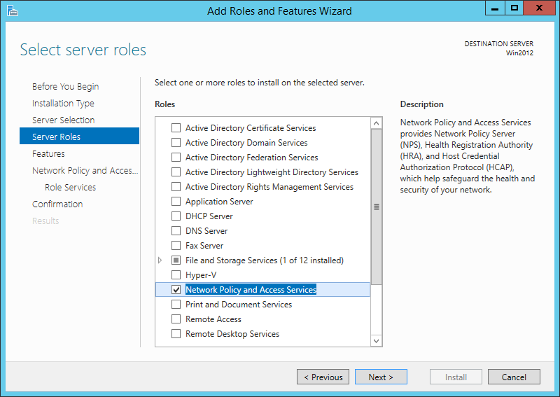
Our radius server will be Microsoft NPS. You can activate this role on the Windows server:
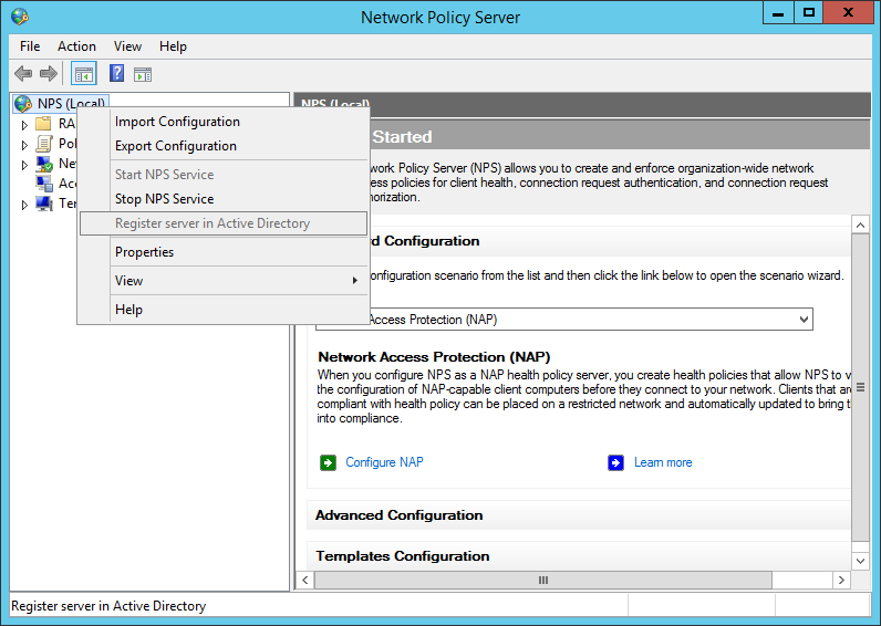
After the installation, open the NPS console and register the radius server in your Active Directory:
add your switches or your management network as a radius-client:
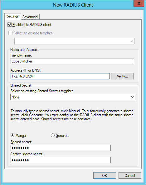
the shared secret will be used in the switch configuration. In created two groups within my test environment:
- “ VLAN2-802.1x ” containing computer accounts
- “ VLAN3-MAC-Auth ” containing user accounts (username+password = mac-address of the device)
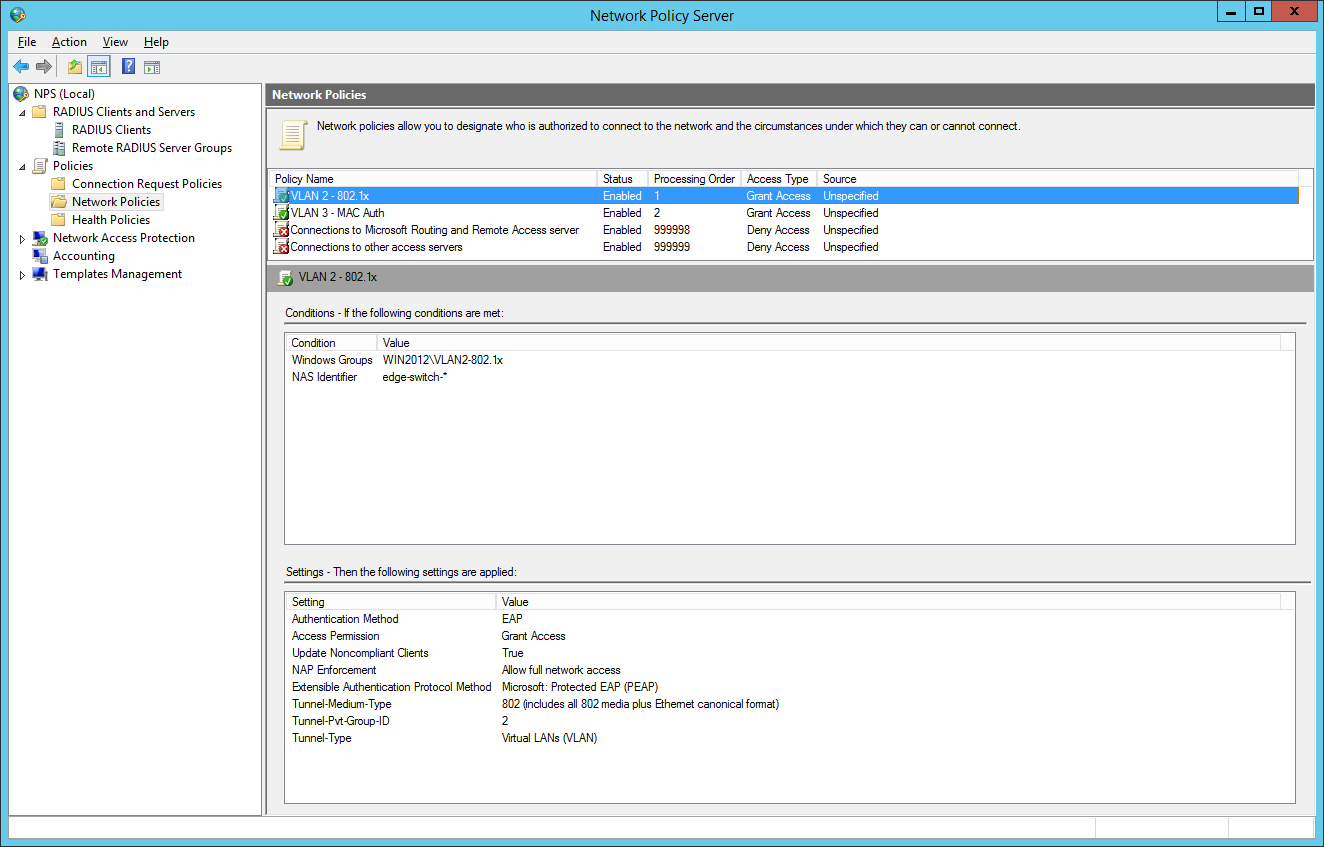
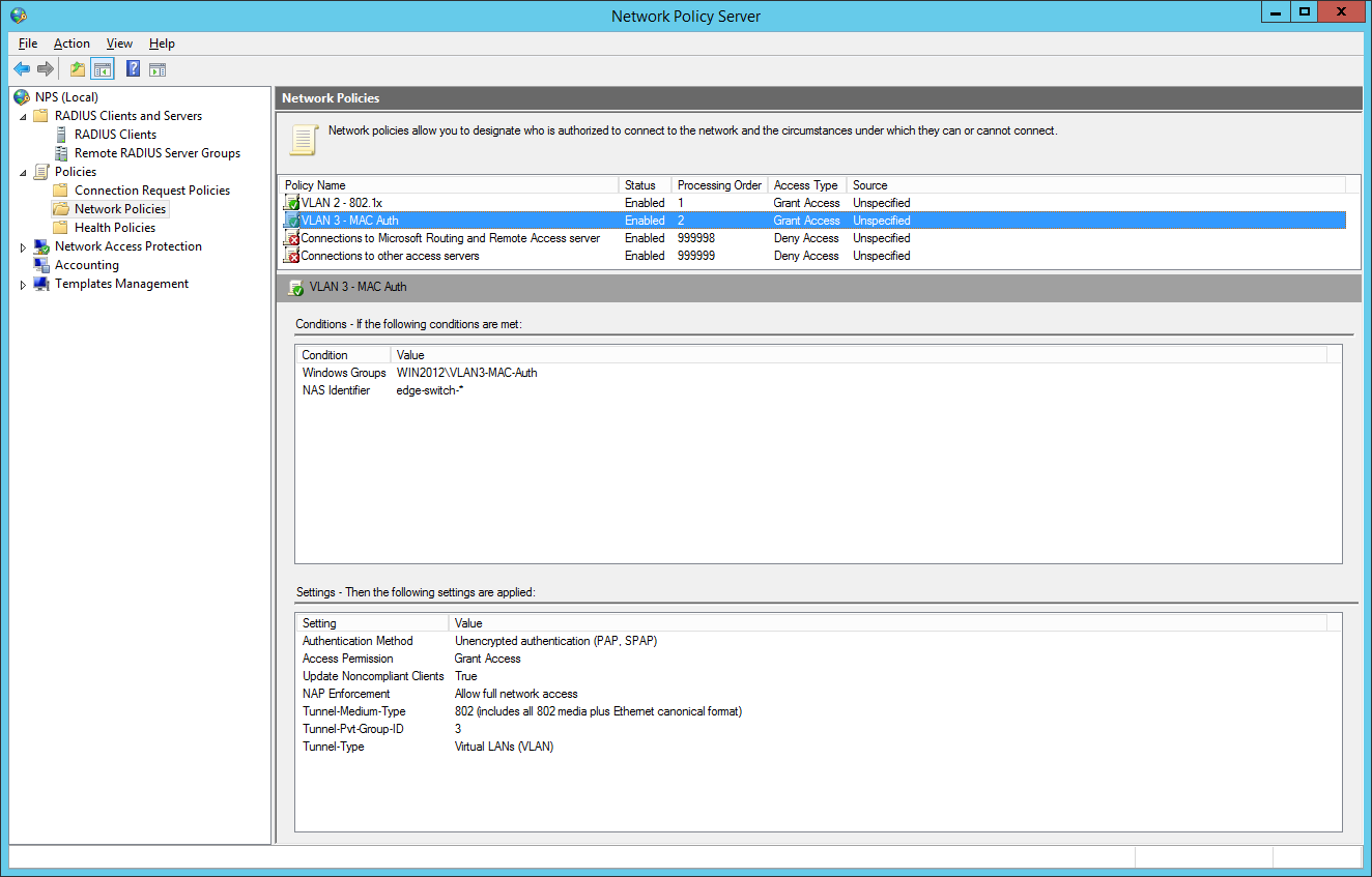
So we will now configure two network policies for our network access control:

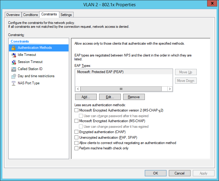
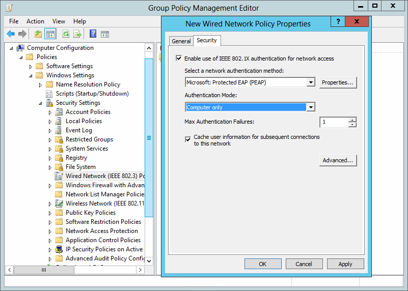
I also configured a NAS Identifier so no other device can use the radius server. The clients will use their computer certificate so you will need a running internal certification authority. Choose PEAP only as the authentication method:
the next step is for our dynamic VLAN assignment. Dot1x devices are bound to VLAN 2:
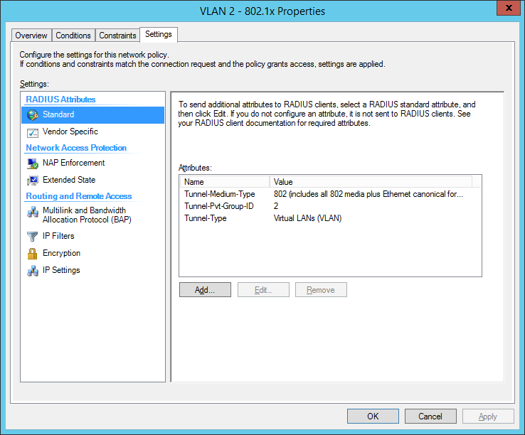
the final dot1x configuration in the NPS:
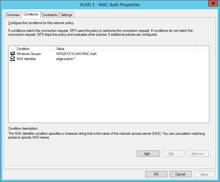
the second network policy is for the mac-based authentication:
Comware switches are sending MAC-Auth-requests via PAP (maybe you know how to change it to CHAP):
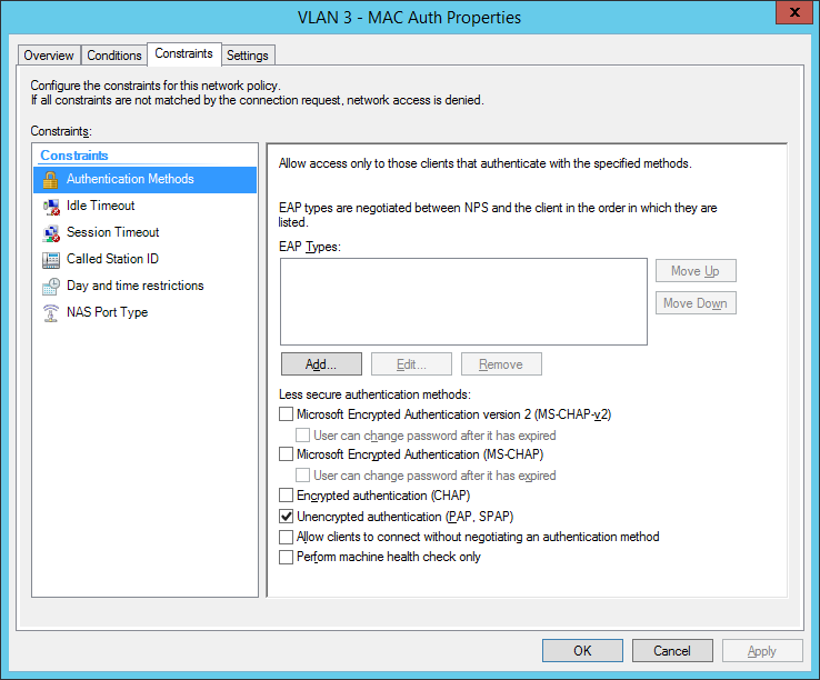
final MAC auth profile:
for now we have built up our authentication server. Now let’s go to the switch configuration. You have global configuration parameters and parameters for each interface. The best way is to use interface-range command to be safe at your configuration. Users who cant authenticate, will be forced to VLAN 999 (quarantine VLAN with no gateway). Here are the global parameters with explanations inline:
now we will configure the interfaces: Added 2 entries
the last part is to configure all windows clients to send 802.1x auth data to the cable network. I’ve done this via a global group policy. You can find the settings under Computer Configuration / Policies / Windows Settings / Security Settings / Wired Network (IEEE 802.3) Policies:
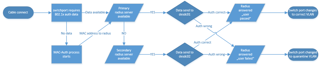
So how does a working 802.1x-auth looks like?
%Jan 3 01:59:59:531 2013 edge-switch-01 DOT1X/6/DOT1X_LOGIN_SUCC: -IfName=GigabitEthernet1/0/10-MACAddr=0023-2415-42a3-AccessVLANID=1- AuthorizationVLANID=2 -Username= host/PC123.mycompany.local ; User passed 802.1X authentication and came online.
Successful Mac-Authentication of a printer:
%Jan 3 01:31:28:782 2013 de-pad-l19-edg01 MACA/6/MACA_LOGIN_SUCC: -IfName=GigabitEthernet1/0/9-MACAddr=0017-c82d-e9bf-AccessVLANID=1- AuthorizationVLANID=3 -Username= 0017c82de9bf -UsernameFormat=MAC address; User passed MAC authentication and came online.
I tried to draw a flow chart which shows the authentication process, I hope it’s ok for you :)
Do you have questions? Feel free to write them into the comments and I will try to answer.
Have a nice and sunny day!
/edit: If you can’t see success and failure events, follow this instruction: NPS / Radius Server is not logging
/edit 2018-05-14: I corrected the global and interface configuration, we had problems with the old configuration
12 Responses
Thanks for this, I need to setup dynamic VLAN assignment in the near future but for Juniper equipment.
This at least gives me a good starting point, thanks for the write up.
Many thanks for the perfect tutorial on How to use 802.1x/Mac-Auth and dynamic VLAN assignment. Many of us can take help from it. Really nice.
Nice write-up. This was a great starting point for configuring the base for dynamic polices. Thanks!
hi Mike, how ‘s about hybrid port with voice-vlan? does it work?
thanks Tung Duong
we had several problems with this config, currently we are investigating hyprid ports with “port security” command. I will update this post if we have prooved this version.
Can you tell me why I would do this over conventional static VLANs? What are the benefits radius dynamic VLANs?
we have customers which want to divide the network for clients, printers and “special devices”. So you have different group/radius-policies to directly place the devices in the right VLAN. Dynamic VLAN is only a bonus feature which you can use. Of course, you can use only the 802.1x and Mac authentication for security purpose.
I’m on the desktop side of things, so apologies if I use any incorrect terminology here.
Our Infrastructure team are looking at introducing 8021x in our schools. They have a test setup where all 8021x devices pick up a data centre VLAN regardless of which building they’re in – eg 10.100.50.
Each building WIRED has its own unique IP – SchoolA=10.120, SchoolB = 10.130 and so on.
I’ve asked if the 8021x setup can be where 8021x devices in SchoolA will get 10.120.50; SchoolB will get 10.130.50
This would allow us to easily determine which building LaptopA actually is, in the same way as we can with our wired desktops. It also saves on SCCM boundary issues causing applications/updates to be pulled over the WAN rather than the LAN.
It’s been suggested that this may not be possible. Could someone confirm this?
Thanks in advance.
Hello! This is of course possible!
My idea (with examples):
SchoolA=10.120 (Location: Chicago) SchoolB=10.130 (Location: Dallas)
So at Chicago you will have VLAN 333, every device is getting an IP address with 10.120.x.x. At Dallas every device in VLAN 333 is getting an IP address with 10.130.x.x. So the VLAN ID “333” is the same at every school but the DHCP scope and default gateway has it’s own address. So the device is getting the VLAN 333 at every location but another IP address. It’s very simple.
It’s not working if all schools are connected via Layer2 so VLAN333 can’t be a “standalone VLAN” at each geographical location.
Ask me any questions, I will try to help you.
- Pingback: 802.1x, MAC-Authentication and VLAN assignment at ProCurve/aruba Switches – Network Guy
- Pingback: Port Auth, Dynamic VLAN and Radius | samuelnotes
- Pingback: HPE Comware problem with mac authentication and printer - Network Guy
Leave a Reply Cancel reply
Click on the button to load the content from jetpack.wordpress.com.
Load content
This site uses Akismet to reduce spam. Learn how your comment data is processed .
Certificates

Post Categories
Post archives, recent posts.
- Sophos UTM 9.712-13 HA update problem 14. November 2022
- Sophos UTM 9.712-12 update released 24. August 2022
- Aruba OS Switch automatic vlan assignment for aruba APs 5. May 2022
- Sophos UTM 9.711-5 update released 22. April 2022
- Sophos UTM 9.710-1 update released 20. March 2022
Recent Comments
- Sophos Ssl Vpn Client Anmeldung - Login and Portal on Auto-Logon with Sophos SSL VPN Client (OpenVPN)
- Russell on Install Sophos UTM from USB Stick
- arno on Problems with incoming mails
- GigaTech IT on Installing Realtek Driver on ESXi 6.7
- Sophos User Portal Login Ssl Vpn - Online Login on Auto-Logon with Sophos SSL VPN Client (OpenVPN)
Franky’s Web Website from my friend Frank. News and Tricks about Microsoft products, primarly Exchange Server
Copyright by networkguy.de
Imprint · Privacy Policy
MAC-based VLANs
The MAC-based VLAN feature assigns hosts to a VLAN based on their MAC addresses. This feature is also called user-based VLAN because VLAN configuration remains the same regardless of a user's physical location.
Static MAC-based VLAN assignment
Use static MAC-based VLAN assignment in networks that have a small number of VLAN users. To configure static MAC-based VLAN assignment on a port, perform the following tasks:
Create MAC-to-VLAN entries.
Enable the MAC-based VLAN feature on the port.
Assign the port to the MAC-based VLAN.
A port configured with static MAC-based VLAN assignment processes a received frame as follows before sending the frame out:
For an untagged frame, the port determines its VLAN ID in the following workflow:
The port first performs a fuzzy match as follows:
Searches for the MAC-to-VLAN entries whose masks are not all Fs.
Performs a logical AND operation on the source MAC address and each of these masks.
If an AND operation result matches the MAC address in a MAC-to-VLAN entry, the port tags the frame with the VLAN ID specific to this entry.
If the fuzzy match fails, the port performs an exact match. It searches for MAC-to-VLAN entries whose masks are all Fs. If the source MAC address of the frame exactly matches the MAC address of a MAC-to-VLAN entry, the port tags the frame with the VLAN ID specific to this entry.
If no matching VLAN ID is found, the port determines the VLAN for the packet by using the following matching order:
IP subnet-based VLAN.
Protocol-based VLAN.
Port-based VLAN.
When a match is found, the port tags the packet with the matching VLAN ID.
For a tagged frame, the port determines whether the VLAN ID of the frame is permitted on the port.
If the VLAN ID of the frame is permitted on the port, the port forwards the frame.
If the VLAN ID of the frame is not permitted on the port, the port drops the frame.
Dynamic MAC-based VLAN assignment
When you cannot determine the target MAC-based VLANs of a port, use dynamic MAC-based VLAN assignment on the port. To use dynamic MAC-based VLAN assignment, perform the following tasks:
Enable dynamic MAC-based VLAN assignment on the port.
Dynamic MAC-based VLAN assignment uses the following workflow, as shown in Figure 59 :
When a port receives a frame, it first determines whether the frame is tagged.
If the frame is tagged, the port gets the source MAC address of the frame.
If the frame is untagged, the port selects a VLAN for the frame by using the following matching order:
MAC-based VLAN (fuzzy and exact MAC address match).
After tagging the frame with the selected VLAN, the port gets the source MAC address of the frame.
The port uses the source MAC address and VLAN of the frame to match the MAC-to VLAN entries.
If the source MAC address of the frame exactly matches the MAC address in a MAC-to-VLAN entry, the port checks whether the VLAN ID of the frame matches the VLAN in the entry.
If the two VLAN IDs match, the port joins the VLAN and forwards the frame.
If the two VLAN IDs do not match, the port drops the frame.
If the source MAC address of the frame does not exactly match any MAC addresses in MAC-to-VLAN entries, the port checks whether the VLAN ID of the frame is its PVID.
If the VLAN ID of the frame is the PVID of the port, the port determines whether it allows the PVID.
If the PVID is allowed, the port forwards the frame within the PVID. If the PVID is not allowed, the port drops the frame.
If the VLAN ID of the frame is not the PVID of the port, the port determines whether the VLAN ID is the primary VLAN ID and the port PVID is a secondary VLAN ID. If yes, the port forwards the frame. Otherwise, the port drops the frame.
Figure 59: Flowchart for processing a frame in dynamic MAC-based VLAN assignment

Server-assigned MAC-based VLAN
Use this feature with access authentication, such as MAC-based 802.1X authentication, to implement secure and flexible terminal access.
To implement server-assigned MAC-based VLAN, perform the following tasks:
Configure the server-assigned MAC-based VLAN feature on the access device.
Configure username-to-VLAN entries on the access authentication server.
When a user passes authentication of the access authentication server, the server assigns the authorization VLAN information for the user to the device. The device then performs the following operations:
Generates a MAC-to-VLAN entry by using the source MAC address of the user packet and the authorization VLAN information. The authorization VLAN is a MAC-based VLAN.
The generated MAC-to-VLAN entry cannot conflict with the existing static MAC-to-VLAN entries. If a confliction exists, the dynamic MAC-to-VLAN entry cannot be generated.
Assigns the port that connects the user to the MAC-based VLAN.
When the user goes offline, the device automatically deletes the MAC-to-VLAN entry and removes the port from the MAC-based VLAN. For more information about 802.1X and MAC authentication, see Security Configuration Guide .
© Copyright 2018 Hewlett Packard Enterprise Development LP
Thank you for taking the time to respond. The NETGEAR documentation team uses your feedback to improve our knowledge base content.
Rating Submitted
Do you have a suggestion for improving this article?
Characters Left : 500
MyNETGEAR® Account
Welcome back
Access your NETGEAR

NETGEAR Support
How do I assign a MAC-based VLAN using the web interface on my managed switch?
Was this article helpful? Yes No

- In the VLAN ID field, enter 3 .
- In the VLAN Name field, enter VLAN3 .
- In the VLAN Type list, select Static .
- Click Add .

- In the VLAN ID list, select 3 .
- Click Unit 1 . The ports display.
- Click the gray box before Unit 1 until U displays.
- Click Apply .

- Scroll down and select the 1/0/23 check box.
- In the PVID (1 to 4093) field, enter 3 .
- Click Apply to save the settings.

- In the MAC Address field, enter 00:00:0A:00:00:02 .
- In the PVID (1 to 4093) field, enter 3 .
- Click Add .
For more information, see the following support articles:
- What is a virtual LAN (VLAN) and how does it work with my managed switch?
- What is a MAC-based VLAN and how does it work with my managed switch?
- How do I create a MAC-based VLAN using CLI commands on my managed switch?
This article applies to the following managed switches and their respective firmware:
- M5300 - firmware version 10.0.0.x
- M5300-28G (GSM7228S)
- M5300-5G (GSM7252S)
- M5300-28G3 (GSM7328Sv2h2)
- M5300-52G3 (GSM7352Sv2h2)
- M5300-28G_POE+ (GSM7228PSv1h2)
- M5300-52G-POE+ (GSM7252PSv1h2)
- M5300-28GF3 (GSM7328FSv2)
- M4100 - firmware version 10.0.1.x
- M4100-26G (GSM7224v2h2)
- M4100-50G (GSM7248v2h2)
- M4100-26G-POE (GSM7226Pv1h1)
- M4100-50G-POE+ (GSM7248Pv1h1)
- M4100-26G-POE (FSM7226Pv1h1)
- M4100-50-POE (FSM7250Pv1h1)
- M4100-D12G (GSM5212v1h1)
- M4100-D10-POE (FSM5210Pv1h1)
- M7100 - firmware version 10.0.1.x
- M7100-24X (XSM7224)
- XSM7224S - firmware version 9.0.1.x
Last Updated:03/10/2023 | Article ID: 21597
Was this article helpful?
This article applies to:.
- M4200-10MG-PoE+ (GSM4210P)
- M4250-10G2F-PoE+ (GSM4212P)
- M4250-10G2XF-PoE+ (GSM4212PX)
- M4250-10G2XF-PoE++ (GSM4212UX)
- M4250-12M2XF (MSM4214X)
- M4250-16XF (XSM4216F)
- M4250-26G4F-PoE+ (GSM4230P)
- M4250-26G4F-PoE++ (GSM4230UP)
- M4250-26G4XF-PoE+ (GSM4230PX)
- M4250-40G8F-PoE+ (GSM4248P)
- M4250-40G8XF-PoE+ (GSM4248PX)
- M4250-40G8XF-PoE++ (GSM4248UX)
- M4250-8G2XF-PoE+ (GSM4210PX)
- M4250-9G1F-PoE+ (GSM4210PD)
- M4300-12X12F (XSM4324S)
- M4300-16X (XSM4316PA)
- M4300-16X (XSM4316PB)
- M4300-24X (XSM4324CS)
- M4300-24X24F (XSM4348S)
- M4300-24XF (XSM4324FS)
- M4300-28G (GSM4328S)
- M4300-28G-PoE+ (GSM4328PA)
- M4300-28G-PoE+ (GSM4328PB)
- M4300-48X (XSM4348CS)
- M4300-48XF (XSM4348FS)
- M4300-52G (GSM4352S)
- M4300-52G-PoE+ (GSM4352PA)
- M4300-52G-PoE+ (GSM4352PB)
- M4300-8X8F (XSM4316S)
- M5300-28G-POE+ (GSM7228PSv1h2)
- M5300-52G (GSM7252S)
- M7300-24XF (XSM7224S)
- M4100-26-POE (FSM7226Pv1h1)
- M4100-26G-POE (GSM7226LPv1h1)
Looking for more about your product?
Get information, documentation, videos and more for your specific product.
Can’t find what you’re looking for?
Quick and easy solutions are available for you in the NETGEAR community.
Need to Contact NETGEAR Support?
With NETGEAR’s round-the-clock premium support, help is just a phone call away.
Complimentary Support
NETGEAR provides complimentary technical support for NETGEAR products for 90 days from the original date of purchase.
NETGEAR Premium Support
Gearhead support for home users.
GearHead Support is a technical support service for NETGEAR devices and all other connected devices in your home. Advanced remote support tools are used to fix issues on any of your devices. The service includes support for the following:
- Desktop and Notebook PCs, Wired and Wireless Routers, Modems, Printers, Scanners, Fax Machines, USB devices and Sound Cards
- Windows Operating Systems (2000, XP or Vista), MS Word, Excel, PowerPoint, Outlook and Adobe Acrobat
- Anti-virus and Anti-Spyware: McAfee, Norton, AVG, eTrust and BitDefender
ProSUPPORT Services for Business Users
NETGEAR ProSUPPORT services are available to supplement your technical support and warranty entitlements. NETGEAR offers a variety of ProSUPPORT services that allow you to access NETGEAR's expertise in a way that best meets your needs:
- Product Installation
- Professional Wireless Site Survey
- Defective Drive Retention (DDR) Service
Where to Find Your Model Number
To find the model/version number, check the bottom or back panel of your NETGEAR device.
Select a product or category below for specific instructions.

Nighthawk Routers

Powerline and Wall Plug Extenders

Cable and DSL Modem Routers

ReadyNAS Network Storage

Wireless Access Points

Other Business Products

Mobile Broadband
Understanding VLAN Assignments
A client is assigned to a VLAN by one of several methods, in order of precedence. The assignment of VLANs are (from lowest to highest precedence):
Tunnel-Type="VLAN"(13)
Tunnel-Medium-Type="IEEE-802" (6)
Tunnel-Private-Group-Id="101"
Aruba -User-VLAN
Aruba -Named-User-VLAN
VLAN Derivation Priorities for VLAN types
The VLAN derivation priorities for VLAN is defined below in the increasing order:
Use the following command to display user VLAN derivation related debug information:
(host) #show aaa debug vlan user [ip | ipv6 | mac]
How a VLAN Obtains an IP Address
A VLAN on the controller obtains its IP address in one of the following ways:
Assigning a Static Address to a VLAN
You can manually assign a static IP address to a VLAN on the controller . At least one VLAN on the controller a static IP address.
In the WebUI
(host)(config) # interface vlan < id>
ip address < address> < netmask>
Configuring a VLAN to Receive a Dynamic Address
In a branch office, you can connect a controller to an uplink switch or server that dynamically assigns IP addresses to connected devices. For example, you can connect the controller to a DSL or cable modem, or a broadband remote access server (BRAS). The following figure shows a branch office where a controller connects to a cable modem. VLAN 1 has a static IP address, while VLAN 2 has a dynamic IP address assigned via DHCP or PPPoE from the uplink device.
Figure 1 IP Address Assignment to VLAN via DHCP or PPPoE

Configuring Multiple Wired Uplink Interfaces (Active-Standby)
You can assign up to four VLAN interfaces to operate in active-standby topology. An active-standby topology provides redundancy so that when an active interface fails, the user traffic can failover to the standby interface.
To allow the controller to obtain a dynamic IP address for a VLAN, enable the DHCP or PPPoE client on the controller for the VLAN.
The following restrictions apply when enabling the DHCP or PPPoE client on the controller :
Enabling the DHCP Client
The DHCP server assigns an IP address for a specified amount of time called a lease. The controller automatically renews the lease before it expires. When you shut down the VLAN, the DHCP lease is released.
Figure 2 Assigning VLAN Uplink Priority—Active-Standby Configuration

In this example, the DHCP client has the client ID name myclient , and the interface VLAN 62 has an uplink priority of 2:
(host)(config) #interface vlan 62
(host)(config) #uplink wired vlan 62 priority 2
(host)(config) #interface vlan 62 ip address dhcp-client client-id myclient
Enabling the PPPoE Client
To authenticate the BRAS and request a dynamic IP address, the controller must have the following configured:
When you shut down the VLAN, the PPPoE session terminates.
In this example, a PPoE service name, username, and password are assigned, and the interface VLAN 14 has an uplink priority of 3:
(host)(config) # interface vlan 14
ip address pppoe
(host)(config) # interface vlan 14 ip pppoe-service-name < service_name >
(host)(config) # interface vlan 14 ip pppoe-username < username >
(host)(config) # interface vlan 14 ip pppoe-password *****
(host)(config) # uplink wired vlan 14 priority 3
Default Gateway from DHCP/PPPoE
You can specify that the router IP address obtained from the DHCP or PPPoE server be used as the default gateway for the controller .
(host) (config) # ip default-gateway import
Configuring DNS/WINS Server from DHPC/PPPoE
The DHCP or PPPoE server can also provide the IP address of a DNS server or NetBIOS name server, which can be passed to wireless clients through the controller ’s internal DHCP server.
For example, the following configures the DHCP server on the controller to assign addresses to authenticated employees; the IP address of the DNS server obtained by the controller via DHCP/PPPoE is provided to clients along with their IP address.
Use the following commands:
(host)(config) # ip dhcp pool employee-pool
default-router 10.1.1.254
dns-server import
netbios-name-server import
network 10.1.1.0 255.255.255.0
Configuring Source NAT to Dynamic VLAN Address
When a VLAN interface obtains an IP address through DHCP or PPPoE, a NAT pool (dynamic-srcnat) and a session ACL (dynamic-session-acl) are automatically created which reference the dynamically-assigned IP addresses. This allows you to configure policies that map private local addresses to the public address(es) provided to the DHCP or PPPoE client. Whenever the IP address on the VLAN changes, the dynamic NAT pool address also changes to match the new address.
For example, the following rules for a guest policy deny traffic to internal network addresses. Traffic to other (external) destinations are source NATed to the IP address of the DHCP/PPPoE client on the controller .
(host)(config) # ip access-list session guest
any network 10.1.0.0 255.255.0.0 any deny
any any any src-nat pool dynamic-srcnat
Configuring Source NAT for VLAN Interfaces
The example configuration in the previous section illustrates how to configure source NAT using a policy that is applied to a user role. You can also enable source NAT for a VLAN interface to perform NAT on the source address for all traffic that exits the VLAN.
Starting with ArubaOS 6.4.4, all outbound traffic now can enable NAT with the IP address of the VLAN interface as the source address; while the locally routed traffic is sent without any address translation.
Traditionally, ArubaOS supported only IP NAT Inside feature where traffic performs NAT with the desired IP address of the VLAN interface as the source address which was useful for only traffic going out of uplink VLAN interface. However, for traffic which needed local routing was also going through unnecessary address translation. Now, this feature resolves this issue by allowing only outbound traffic to perform NAT.
Sample Configuration
In the following example, the controller operates within an enterprise network. VLAN 1 is the outside VLAN, and traffic from VLAN 6 is source NATed using the IP address of the controller . The IP address assigned to VLAN 1 is used as the controller ’s IP address; thus traffic from VLAN 6 would be source NATed to 66.1.131.5:
Figure 3 Example: Source NAT using Controller IP Address

(host)(config) # interface vlan 1
ip address 66.1.131.5 255.255.255.0
(host)(config) # interface vlan 6
(host)(config) # ip address 192.168.2.1 255.255.255.0
ip nat inside
ip default-gateway 66.1.131.1
ip nat outside
Inter-VLAN Routing
On the controller , you can map a VLAN to a layer-3 subnetwork by assigning a static IP address and a netmask, or by configuring a DHCP or PPPoE server to provide a dynamic IP address and netmask to the VLAN interface. The controller , acting as a layer-3 switch, routes traffic between VLANs that are mapped to IP subnetworks; this forwarding is enabled by default.
In Figure 4 , VLAN 200 and VLAN 300 are assigned the IP addresses 2.1.1.1/24 and 3.1.1.1/24, respectively. Client A in VLAN 200 is able to access server B in VLAN 300 and vice-versa, provided that there is no firewall rule configured on the controller to prevent the flow of traffic between the VLANs.
Figure 4 Default Inter-VLAN Routing

You can optionally disable layer-3 traffic forwarding to or from a specified VLAN. When you disable layer-3 forwarding on a VLAN, the following restrictions apply:
To disable layer-3 forwarding for a VLAN configured on the controller :
(host)(config) #interface vlan <id>
ip address {<ipaddr> <netmask>|dhcp-client|pppoe}
no ip routing
CloudEngine S5700 V600R022C01 Configuration Guide - Ethernet Switching Configuration
- About This Document
- MAC Configuration
- Eth-Trunk Configuration
- Overview of VLANs
- Understanding VLANs
- Configuration Precautions for VLAN
- Default Settings for VLANs
- Creating and Deleting a VLAN
- Changing and Restoring the Default VLAN
- Configuring a VLANIF Interface
- Understanding Intra-VLAN Communication
- Configuring Interface-based VLAN Assignment
Configuring MAC Address-based VLAN Assignment
- Configuring Subnet-based VLAN Assignment
- Configuring Protocol-based VLAN Assignment
- Example for Configuring Interface-based VLAN Assignment to Implement Intra-VLAN Communication (Through a Single Device)
- Example for Configuring Interface-based VLAN Assignment to Implement Intra-VLAN Communication (Through Multiple Devices)
- Example for Configuring Interface-based VLAN Assignment and VLANIF Interfaces to Implement Communication Across Network Segments (Through Multiple Devices)
- Example for Configuring MAC Address-based VLAN Assignment
- Example for Configuring Subnet-based VLAN Assignment
- Example for Configuring Protocol-based VLAN Assignment
- Configuring Inter-VLAN Communication
- Configuring a Management VLAN
- Configuring a VLAN Pool
- Configuring VLAN Aggregation
- Configuring MUX VLAN
- Configuring VLAN Mapping
- Configuring QinQ
- Configuring a Voice VLAN
- Configuring Unknown Packet Isolation in a VLAN
- Configuring Transparent Transmission in a VLAN
- Configuring an Interface to Discard Incoming VLAN-Tagged Packets
- Maintaining VLANs
- Troubleshooting VLANs
- STP/RSTP/MSTP Configuration
- VBST Configuration
- ERPS Configuration
- Layer 2 Protocol Tunneling Configuration
Prerequisites
- Create a VLAN. For details, see Creating and Deleting a VLAN .
In MAC address-based VLAN assignment mode, you do not need to reconfigure VLANs for users when their physical locations change. This improves network access security and flexibility.
In MAC address-based VLAN assignment mode, only untagged packets are processed. For tagged packets, only interface-based VLAN assignment mode is used.
If a matching entry is found, the interface forwards the packet based on the VLAN ID and priority in the entry.
Otherwise, the interface matches the packet according to other matching rules.
An interface enabled with MAC address-based VLAN assignment cannot process protocol packets that need to be sent to the CPU. As such, MAC address-based VLAN assignment is recommended in Layer 2 transparent transmission scenarios.
The MAC address cannot be all Fs, all 0s, or a multicast MAC address.
Determine whether to perform this step based on the current interface working mode.
Only interfaces on the S6730-H-V2 and S5732-H-V2 series can be switched from Layer 3 mode to Layer 2 mode using the portswitch command.
By default, MAC address-based VLAN assignment has a higher priority than subnet-based VLAN assignment.
Verifying the Configuration
Run the display mac-vlan { vlan vlan-id | mac-address { mac-address | all } } command to check information about VLANs assigned based on MAC addresses.
Related Version
S3700&S5700&S6700 V200R022C10SPC500
S3700&S5700&S6700 V200R022C00
S3700&S5700&S6700 V200R021C01
S3700&S5700&S6700 V200R021C00
S3700&S5700&S6700 V200R019C10
S3700&S5700&S6700 V200R005
S3700&S5700&S6700 V100R006C05
Related Documents
CloudEngine S5700 V600R022C01 Configuration Guide - Basic Configuration
CloudEngine S5700 V600R022C01 Configuration Guide - System Monitoring
CloudEngine S5700 V600R022C01 Configuration Guide - Virtualization
Digital Signature File
digtal sigature tool
Meraki Community
- Community Platform Help
- Contact Community Team
- Meraki Documentation
- Meraki DevNet Developer Hub
- Meraki System Status
- Technical Forums
MAC address Based VLAN
- Subscribe to RSS Feed
- Mark Topic as New
- Mark Topic as Read
- Float this Topic for Current User
- Printer Friendly Page

- Mark as New
- Report Inappropriate Content
- All forum topics
- Previous Topic

- New April 1: And we're live! New community look & feel is here!
- March 27: [LAUNCH POSTPONED] Planned downtime for the launch of the new Community look & feel
- March 26: New community look & feel, coming soon!
- Interfaces 216
- Layer 2 230
- Layer 3 163
- Community guidelines
- Cisco privacy
- Khoros privacy
- Terms of service
IMAGES
VIDEO
COMMENTS
mac-address - Specifies the MAC address to be mapped to the VLAN group. This MAC address cannot be assigned to any other VLAN group. prefix-mask - Specifies the prefix of the MAC address. Only a section of the MAC address is looked at (from left to right) and then placed in a group. The lower the length number, the fewer bits are looked at.
To do that, you can create a MAC address-to-VLAN map containing multiple MAC address-to-VLAN entries, and enable the MAC-based VLAN feature and dynamic MAC-based VLAN assignment on the port. Dynamic MAC-based VLAN assignment uses the following workflows. When the port receives a frame, the port first determines whether the frame is tagged.
MAC address-based VLAN assignment. VLANs are assigned based on source MAC addresses of frames. A network administrator preconfigures mappings between MAC addresses and VLAN IDs. When receiving an untagged frame, the switch adds the VLAN tag mapping the MAC address of the frame to the frame. Then the frame is transmitted in the specified VLAN.
Yes No. The MAC-based VLAN feature allows incoming untagged packets to be assigned to a VLAN and thus classify traffic based on the source MAC address of the packet. You define a MAC to VLAN mapping by configuring an entry in the MAC to VLAN table. An entry is specified using a source MAC address and the appropriate VLAN ID.
Now when I connect these two laptops to the network, one lands on the 400 VLAN and gets a 4.x address, and the other lands on the 500 VLAN and gets a 5.x address. These assignments can be changed as easily as group membership. I believe this will be a pretty robust solution for us moving forward.
It is recommended that MAC address-based VLAN assignment should be configured on the hybrid interface. Run port hybrid untagged vlan { { vlan-id1 [ to vlan-id2] } &<1-10> | all} On access and trunk interfaces, MAC address-based VLAN assignment can be used only when the MAC address-based VLAN is the same as the PVID.
In dynamic MAC-based VLAN assignment, the port that receives a packet with an unknown source MAC address can be successfully assigned to the matched VLAN only when the matched VLAN is a static VLAN. With MSTP enabled, if a port is blocked in the MST instance (MSTI) of the target MAC-based VLAN, the port drops the received packets, instead of ...
By default, dynamic MAC-based VLAN assignment is disabled. The VLAN assignment for a port is triggered only when the source MAC address of its receiving packet exactly matches the MAC address in a MAC-to-VLAN entry. 7. (Optional.) Configure the system to assign VLANs based on the MAC address preferentially. vlan precedence mac-vlan
MAC-based VLANs. MAC-Based VLANs (MBVs) allow multiple clients on a single switch port to receive different untagged VLAN assignments. VLAN assignment of untagged traffic is based on the source MAC address rather than the port. Clients receive their untagged VLAN assignment from the RADIUS server. This feature adheres to the requirement that if ...
From the controller GUI, navigate to Monitoring > Wireless > Clients > Select the client MAC address > General > Security Information and look for the VLAN field as shown in the image: From this window, you can observe that this client is assigned to VLAN102 as per the RADIUS attributes configured on the RADIUS server.
configure. Enter global configuration mode. Step 2. mac-vlan mac-address mac-addr vlan vlan-id [description descript] Bind the MAC address to the VLAN. mac-addr: Specify the MAC address of the device in the format of xx:xx:xx:xx:xx:xx. vlan-id: Enter the ID number of the 802.1Q VLAN that will be bound to the MAC VLAN.
Policy-based VLAN assignment (MAC addresses, IP addresses, and interfaces) VLANs are assigned based on policies such as combinations of interfaces, MAC addresses, and IP addresses. A network administrator preconfigures policies. When receiving an untagged frame that matches a configured policy, the switch adds a specified VLAN tag to the frame.
The 802.1x protocol is used for network access control. For devices like printers, cameras, etc. we will use mac-authentication as a fallback. We will also use dynamic VLAN assignment for the connected ports. Our radius server will be Microsoft NPS. You can activate this role on the Windows server:
Figure 4-11 Networking diagram of configuring MAC address-based VLAN assignment. In this example, interface 1, interface 2, interface 3, and interface 4 represent 10GE 1/0/1, 10GE 1/0/2, 10GE 1/0/3, and 10GE 1/0/4, respectively. Procedure. Create VLAN 10 and associate host MAC addresses with the VLAN.
Use static MAC-based VLAN assignment in networks that have a small number of VLAN users. To configure static MAC-based VLAN assignment on a port, perform the following tasks: ... If the source MAC address of the frame does not exactly match any MAC addresses in MAC-to-VLAN entries, the port checks whether the VLAN ID of the frame is its PVID.
In the VLAN ID field, enter 3. In the VLAN Name field, enter VLAN3. In the VLAN Type list, select Static. Click Add. Assign ports to VLAN3. Select Switching > VLAN > Advanced > VLAN Membership. A screen similar to the following displays. In the VLAN ID list, select 3. Click Unit 1. The ports display. Click the gray box before Unit 1 until U ...
The assignment of VLANs are (from lowest to highest precedence): 1. The default VLAN is the VLAN configured for the WLAN (see Virtual AP Profiles ). 2. Before client authentication, the VLAN can be derived from rules based on client attributes (SSID, BSSID, client MAC, location, and encryption type).
In MAC address-based VLAN assignment mode, you do not need to reconfigure VLANs for users when their physical locations change. This improves network access security and flexibility. In MAC address-based VLAN assignment mode, only untagged packets are processed. For tagged packets, only interface-based VLAN assignment mode is used.
and they worked around the Vlan assignment by configuring the NVR with an interface to the default staff Vlan but with an IP address of the CAM Vlan. i am thinking if i can configure the Meraki switches with auto Vlan assignment for the ports based on the MAC Addresses. is this doable? regards, 0 Kudos Reply. Subscribe. All forum topics ...